5-28
Starting unit and component
0
1
2
3
4
5
6
7
8
9
10
A
4. Install the starter relay, and then connect
the starter relay leads.
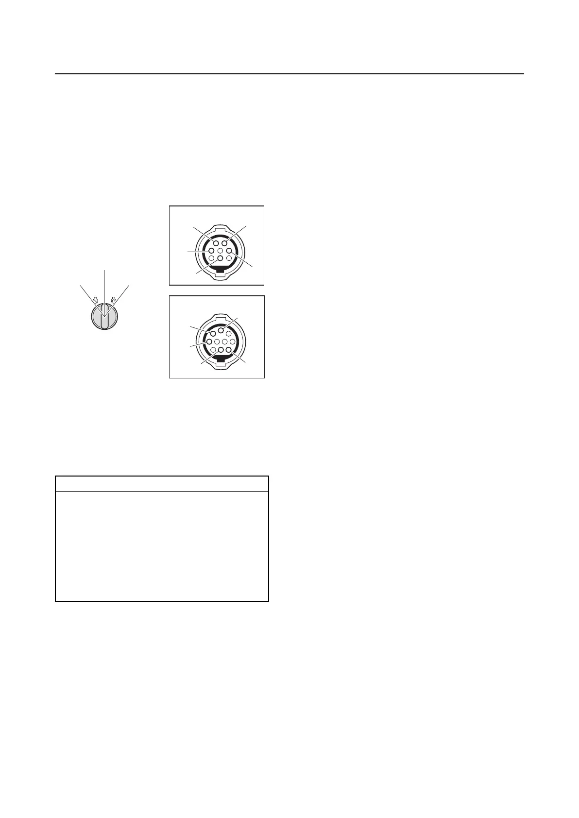
Checking the engine start switch
1. Disconnect the 10-pin coupler or engine
start switch coupler.
2. Check the engine start switch for continu-
ity.
1. OFF
2. ON
3. START
A. 704 remote control
B. 703 remote control
3. Connect the 10-pin coupler or engine
start switch coupler.
Engine start switch continuity:
Switch position OFF:
Terminal “a”–Terminal “b”
Switch position ON:
Terminal “c”–Terminal “d”
Switch position START:
Terminal “c”–Terminal “d”
Terminal “d”–Terminal “e”
Terminal “c”–Terminal “e”
a
a
b
b
c
c
d
d
e
e
B
A
3. START
2. ON
1. OFF