8-17
Propeller shaft housing (regular rotation model)
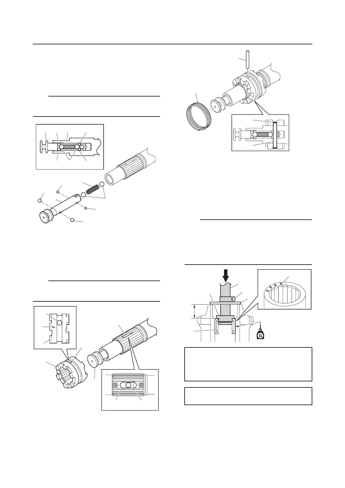
Assembling the propeller shaft
assembly
1. Install the spring “1”, balls “2”, “3”, and
“4”, and slider “5”.
TIP:
When installing the slider “5”, make sure that
the balls do not fall out of position.
2. Install the dog clutch “1” so that the hole
“a” in the dog clutch “1” and the hole “b”
in the propeller shaft are aligned with the
hole “c” in the slider “2”.
TIP:
Face the “F” mark “d” on the dog clutch “1”
toward the slider “2”.
3. Install the cross pin “1”, and then install
the spring “2”.
Assembling the propeller shaft
housing assembly
1. Install a new needle bearing “1” in the
propeller shaft housing at the specified
installation depth “a”.
TIP:
• Face the bearing identification mark “b” on
the needle bearing toward the propeller.
• When using the driver rod, do not strike the
special service tool in a manner that will
force the stopper “5” out of place.
2. Install new oil seals “1” in the propeller
shaft housing at the specified installation
depth “a”.
1
2
3
3
4
4
5
1354
32 4
a
b
c
1
1
a
2
d
b
Driver rod SS “2”: 90890-06604
Needle bearing attachment “3”:
90890-06610
Bearing depth plate “4”: 90890-06603
Installation depth “a”:
24.75–25.25 mm (0.974–0.994 in)
1
2
1
2
a
b
1
2
3
5
4