5-9
ECM circuit
ECM circuit
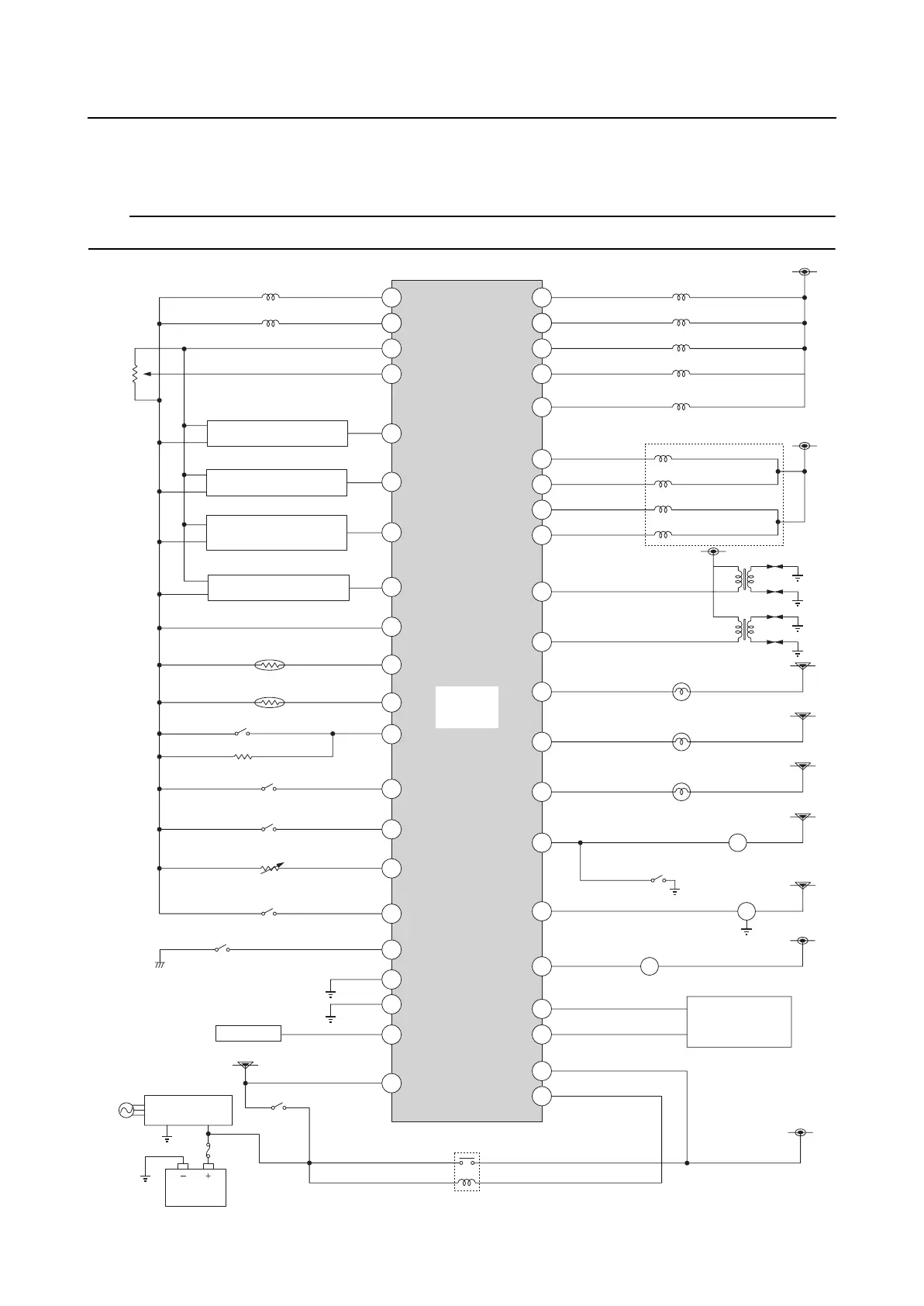
Circuit diagram
TIP:
The circled numbers in the illustration indicate the engine ECM terminal numbers.
21. Engine
ECM
14
15
10
34
33
12
8
35
7
9
4
37
36
5
31
40
39
41
17
22
44
24
28
27
3
2
43
1
23
30
P
BZ
32
42
26
13
20
18
21
19
16
T
1. Pulser coil #1
2. Pulser coil #2
29
11
14. Trim sensor
28. ISC valve
29. Ignition coil #1, 4
30. Ignition coil #2, 3
4. Air pressure sensor
5. Oil pressure sensor
6. Water pressure
sensor
7. Speed sensor
8. Ground
9. Engine temperature sensor
10. Air temperature sensor
11. Shift cut-off switch
13. Thermoswitch
12. Engine shut-off switch
16. Shift position switch
15. Water detection switch
19. Rectifier
Regulator
20. Battery
22. Main relay
18. Engine start switch
38. 6Y8
Multifunction
Meter
37. High-pressure fuel pump
31. Oil pressure alert indicator
32. Overheat alert indicator
36. Tachometer
35. Multi-engine system switch
33. Diagnostic flash indicator
34. Alert buzzer
23. Fuel injector #1
24. Fuel injector #2
25. Fuel injector #3
26. Fuel injector #4
3. TPS
17. YDIS
6
27. Vapor shut-off valve
5V