7-42
Cylinder head
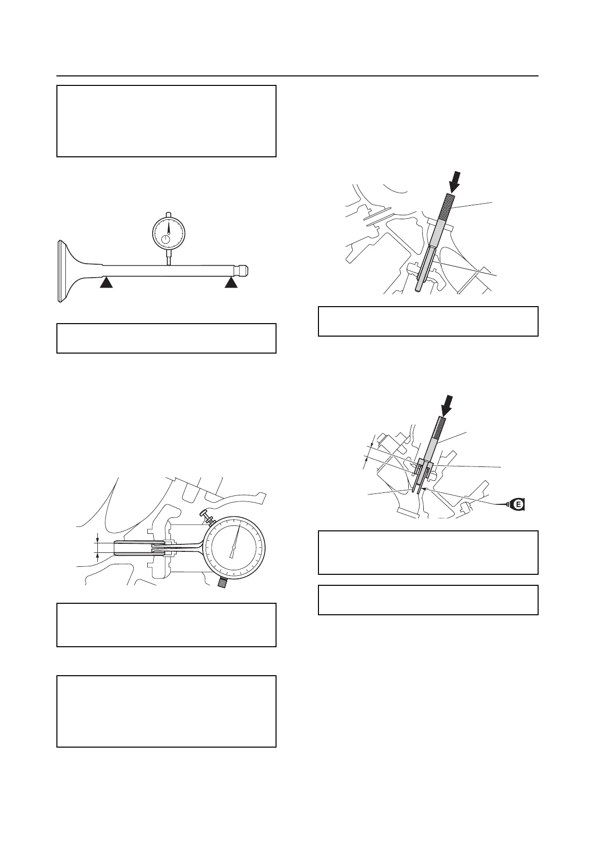
4. Measure the valve stem runout.
Checking the valve guide
Before checking the valve guides, make sure
that the valve stem diameter is within specifi-
cation.
1. Measure the valve guide inside diameter
“a”.
2. Calculate the valve guide clearance.
Replacing the valve guide
After replacing a valve guide, check the valve
seat contact area.
1. Remove the valve guide “1” from the
combustion chamber side.
2. Install a new valve guide “1” from the
camshaft side to the specified installation
height “a”.
3. Insert the special service tool “1” into the
valve guide “2”, and then ream the valve
guide.
Valve stem diameter “a”:
Intake:
5.477–5.492 mm (0.2156–0.2162 in)
Exhaust:
5.464–5.479 mm (0.2151–0.2157 in)
Valve stem runout:
Intake and exhaust: 0.01 mm (0.0004 in)
Valve guide inside diameter “a”:
Intake and exhaust:
5.504–5.522 mm (0.2167–0.2174 in)
Valve guide clearance:
Intake:
0.012–0.045 mm (0.0005–0.0018 in)
Exhaust:
0.025–0.058 mm (0.0010–0.0023 in)
a
Valve guide remover/installer “2”:
90890-06801
Valve guide remover/installer “2”:
90890-06801
Valve guide installer “3”: 90890-06810
Installation height “a”:
11.3–11.7 mm (0.44–0.46 in)
1
2
2
3
a
1