6-44
Vapor separator and high-pressure fuel pump
0
1
2
3
4
5
6
7
8
9
10
A
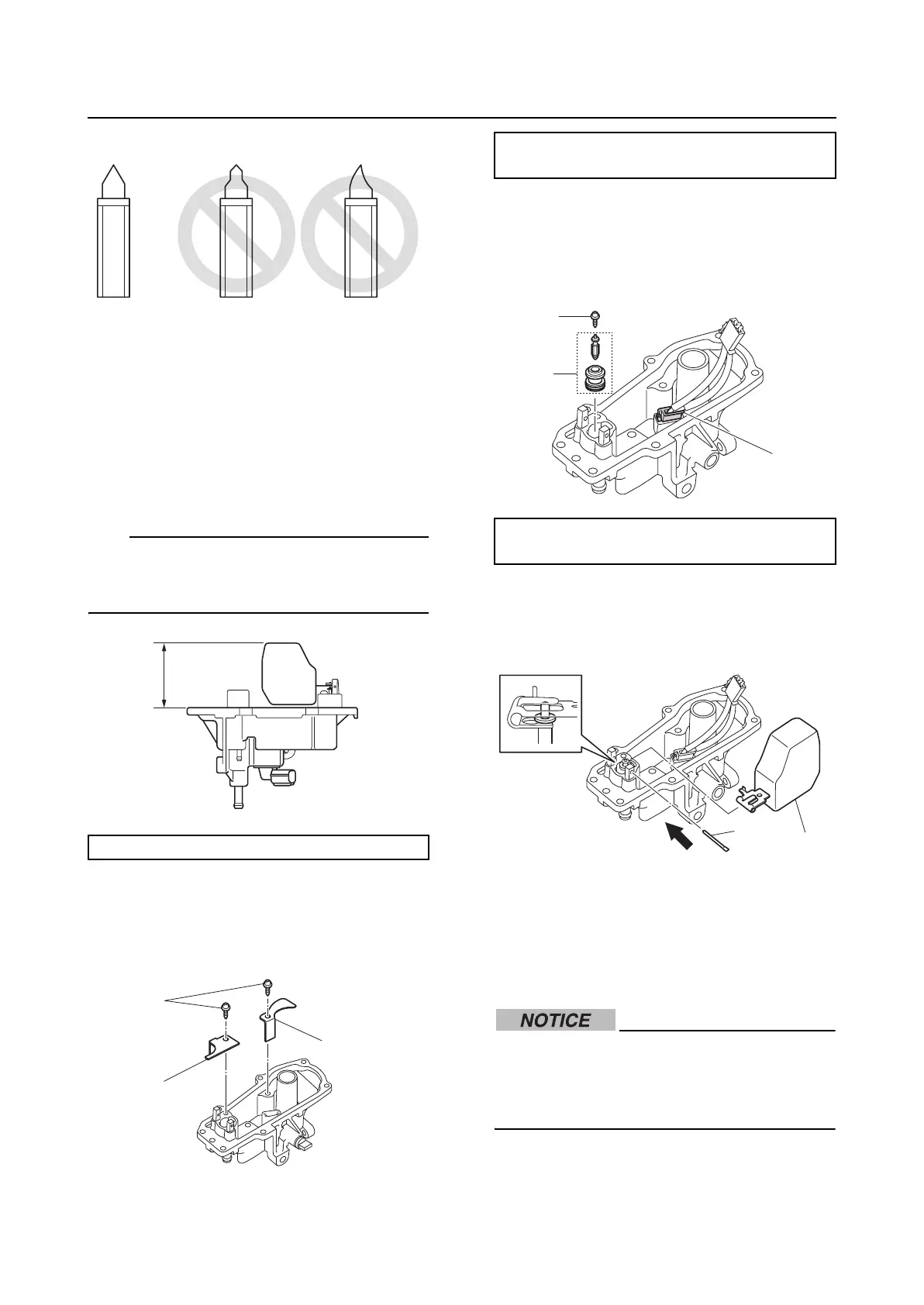
2. Check the float. Replace if deteriorated.
3. Check the filter. Clean if there is dirt or
residue.
4. Place the cover assembly upside down,
and then measure the float height “a”.
TIP:
When measuring the float height, the float
should be resting on the needle valve. Do not
press the float.
Assembling the vapor separator
1. Install the plates “1” and “2”, and then
tighten the float chamber plate screws “3”
to the specified torque.
2. Connect the lead coupler “a”.
3. Install the needle valve assembly “1”, and
then tighten the needle valve screw “2” to
the specified torque.
4. Install the float “1”.
5. Insert the float pin “2” in the direction of
the arrow.
6. Install the filter “1” to the high-pressure
fuel pump “2”.
7. Install the grommet “3”, and then install
the high-pressure fuel pump “2”.
Make sure to install the grommet to the
float chamber cover before installing the
high-pressure fuel pump. Otherwise, the
grommet could be damaged.
8. Connect the lead coupler “a”.
Float height “a”: 55.0–61.0 mm (2.2–2.4 in)
a
1
2
3
Float chamber plate screw “3”:
2 N·m (0.2 kgf·m, 1.5 ft·lb)
Needle valve screw “2”:
2 N·m (0.2 kgf·m, 1.5 ft·lb)
1
2
a
2
1