5-16
Fuel control unit and component
0
1
2
3
4
5
6
7
8
9
10
A
5. Turn the engine start switch to OFF.
6. Connect the ISC valve coupler.
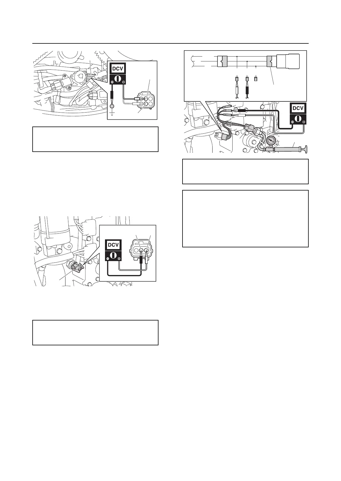
Checking the oil pressure sensor
1. Disconnect the oil pressure sensor cou-
pler “a”.
2. Turn the engine start switch to ON, and
then measure the input voltage at the oil
pressure sensor coupler.
3. Remove the oil pressure sensor, and
then connect the pressure pump “1” and
special service tool “2”.
4. Apply positive pressure to the oil pres-
sure sensor slowly, and then measure
the output voltage at the specified pres-
sures.
5. Turn the engine start switch to OFF, and
then disconnect the special service tool
and pressure pump.
6. Install the oil pressure sensor. See “Cyl-
inder block (F150A, FL150A)” (7-52).
7. Connect the oil pressure sensor coupler.
Fuel control unit and component
Checking the water detection switch
1. Disconnect the water detection switch
coupler “a”.
2. Turn the engine start switch to ON, and
then measure the input voltage at the
water detection switch coupler.
ISC valve input voltage:
Red/Yellow (R/Y)–Ground
12 V (battery voltage)
Oil pressure sensor input voltage:
Orange (O)–Black (B)
4.75 V–5.25 V
R/Y
R/Y
a
a
BO
Pressure pump “1”:
(commercially available)
Test harness (3 pins) “2”: 90890-06869
Oil pressure sensor output voltage
(reference data):
Pink/White (P/W)–Black (B)
2.5 V at 392.0 kPa
(3.92 kgf/cm
2
, 56.8 psi)
4.5 V at 784.0 kPa
(7.84 kgf/cm
2
, 113.7 psi)
P/W
O
B
BG/W G
1
2
2