5-24
Ignition unit and component
0
1
2
3
4
5
6
7
8
9
10
A
9. Install the air temperature sensor, and
then connect the air temperature sensor
coupler.
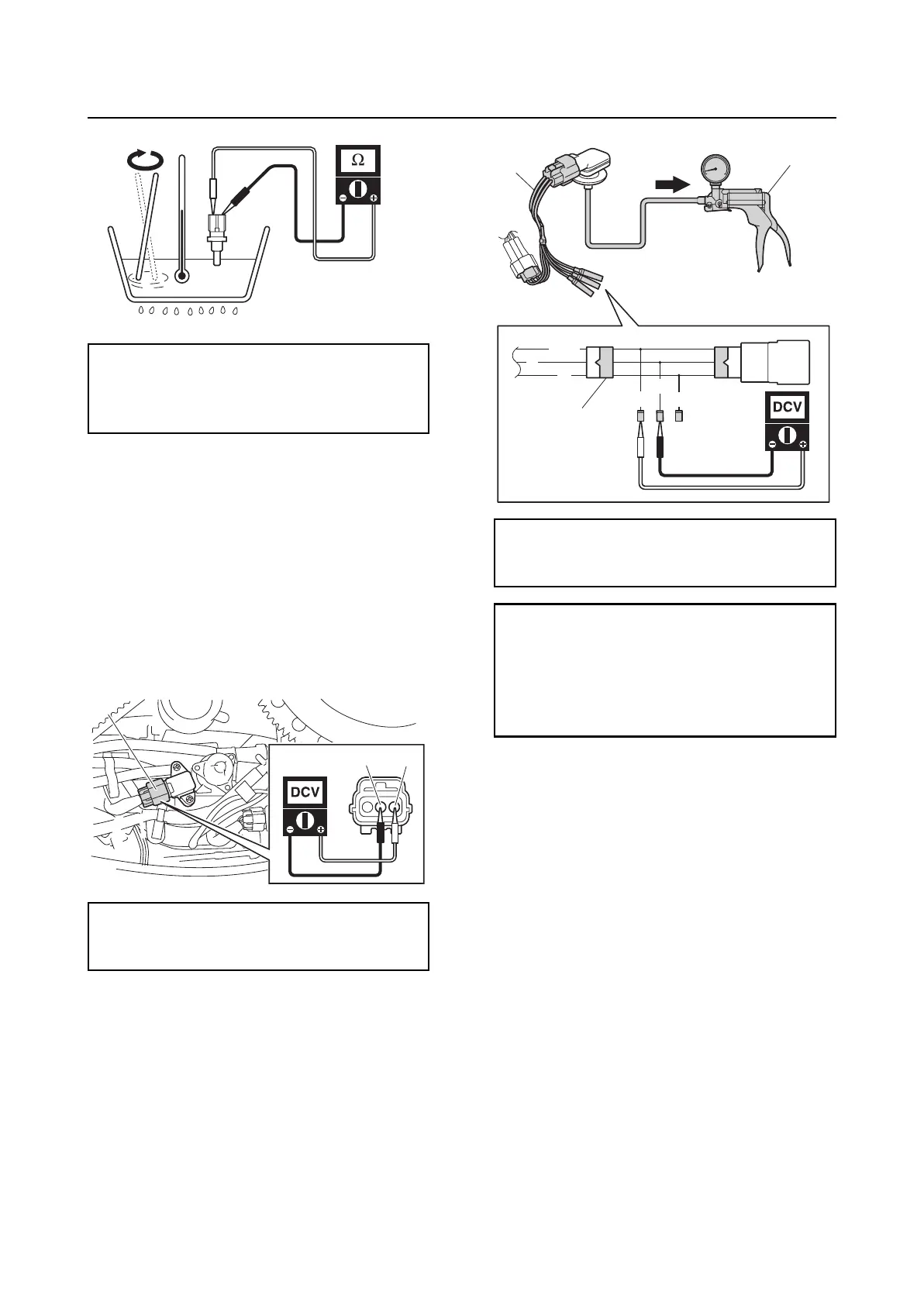
Checking the air pressure sensor
1. Disconnect the air pressure sensor cou-
pler “a”.
2. Turn the engine start switch to ON, and
then measure the input voltage at the air
pressure sensor coupler.
3. Turn the engine start switch to OFF.
4. Remove the air pressure sensor.
5. Connect the special service tools “1” and
“2”.
6. Apply negative pressure to the air pres-
sure sensor slowly, and then measure
the output voltage.
7. Turn the engine start switch to OFF.
8. Disconnect the special service tools.
9. Install the air pressure sensor. See
“Intake manifold and vapor separator” (6-
34).
10. Connect the air pressure sensor coupler.
Checking the engine temperature
sensor
1. Disconnect the engine temperature sen-
sor coupler “a”.
2. Turn the engine start switch to ON, and
then measure the input voltage at the
engine temperature sensor coupler.
Air temperature sensor resistance
(reference data):
2.2–2.7 kΩ at 20 °C (68 °F)
0.32 kΩ at 80 °C (176 °F)
Air pressure sensor input voltage:
Orange (O)–Black (B)
4.75–5.25 V
a
BO
Vacuum/pressure pump gauge set “1”:
90890-06945
Test harness (3 pins) “2”: 90890-06869
Air pressure sensor output voltage:
Pink/Green (P/G)–Black (B)
3.21 V at –20.0 kPa
(–0.20 kgf/cm
2
, –2.9 psi)
2.16 V at –46.7 kPa
(–0.467 kgf/cm
2
, –6.8 psi)
B
G/W
G
P/G
B
O
1
2
2