8-28
Drive shaft and lower case (regular rotation model)
0
1
2
3
4
5
6
7
8
9
10
A
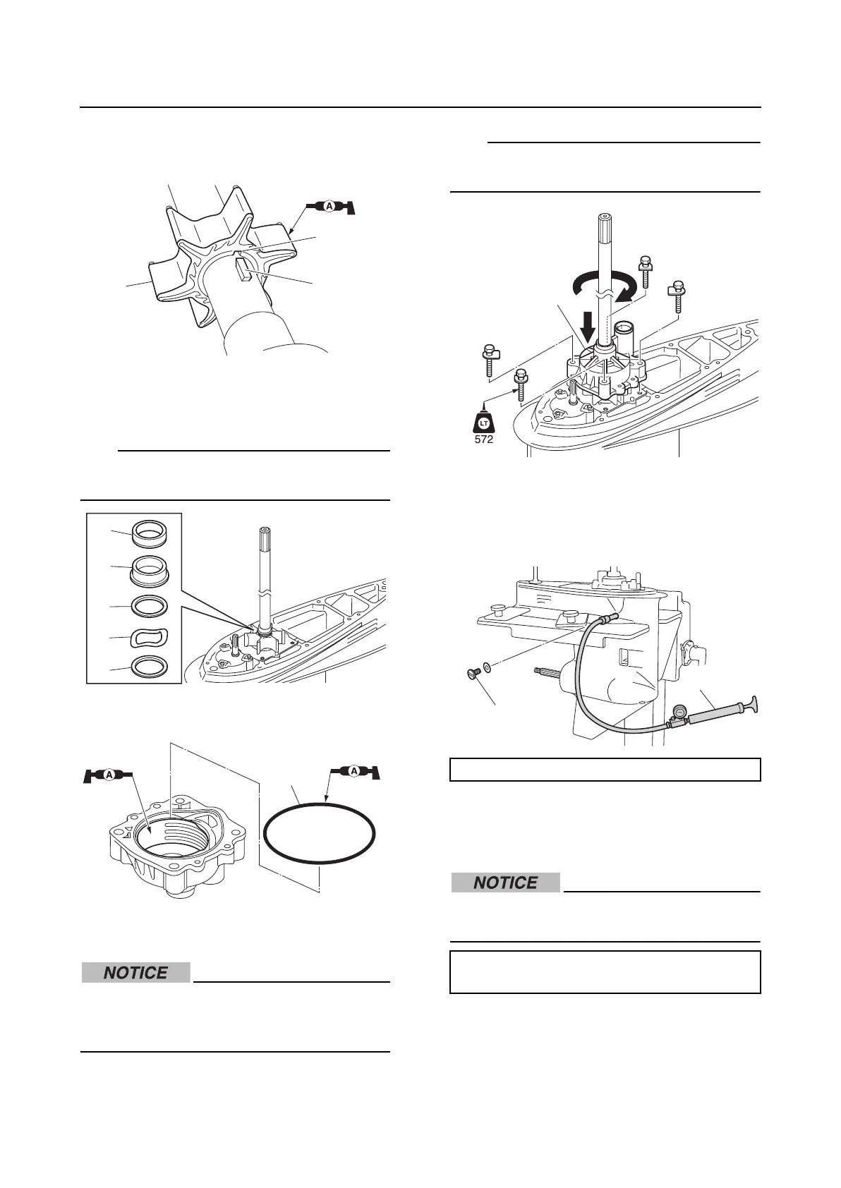
4. Align the slot “a” in the impeller “2” with
the Woodruff key “1”, and then install the
impeller “2”.
5. Install the washers “1”, wave washer “2”,
spacer “3”, and collar “4”.
TIP:
The spacer “3” and collar “4” should fit
together firmly.
6. Install a new O-ring “1”.
7. Install the water pump housing “1”.
Do not turn the drive shaft counterclock-
wise. Otherwise, the water pump impeller
could be damaged.
TIP:
While turning the drive shaft clockwise, push
the water pump housing down to install it.
Checking the lower unit for air
leakage
1. Remove the check screw “1”, and then
install the special service tool “2”.
2. Apply the specified pressure. Check that
the pressure is maintained in the lower
unit for 10 seconds or more.
Do not overpressurize the lower unit. Oth-
erwise, the oil seals could be damaged.
1
2
a
1
1
2
3
4
1
Leakage tester “2”: 90890-06840
Lower unit holding pressure:
69.0 kPa (0.69 kgf/cm
2
, 10.0 psi)
1
1
2