9-9
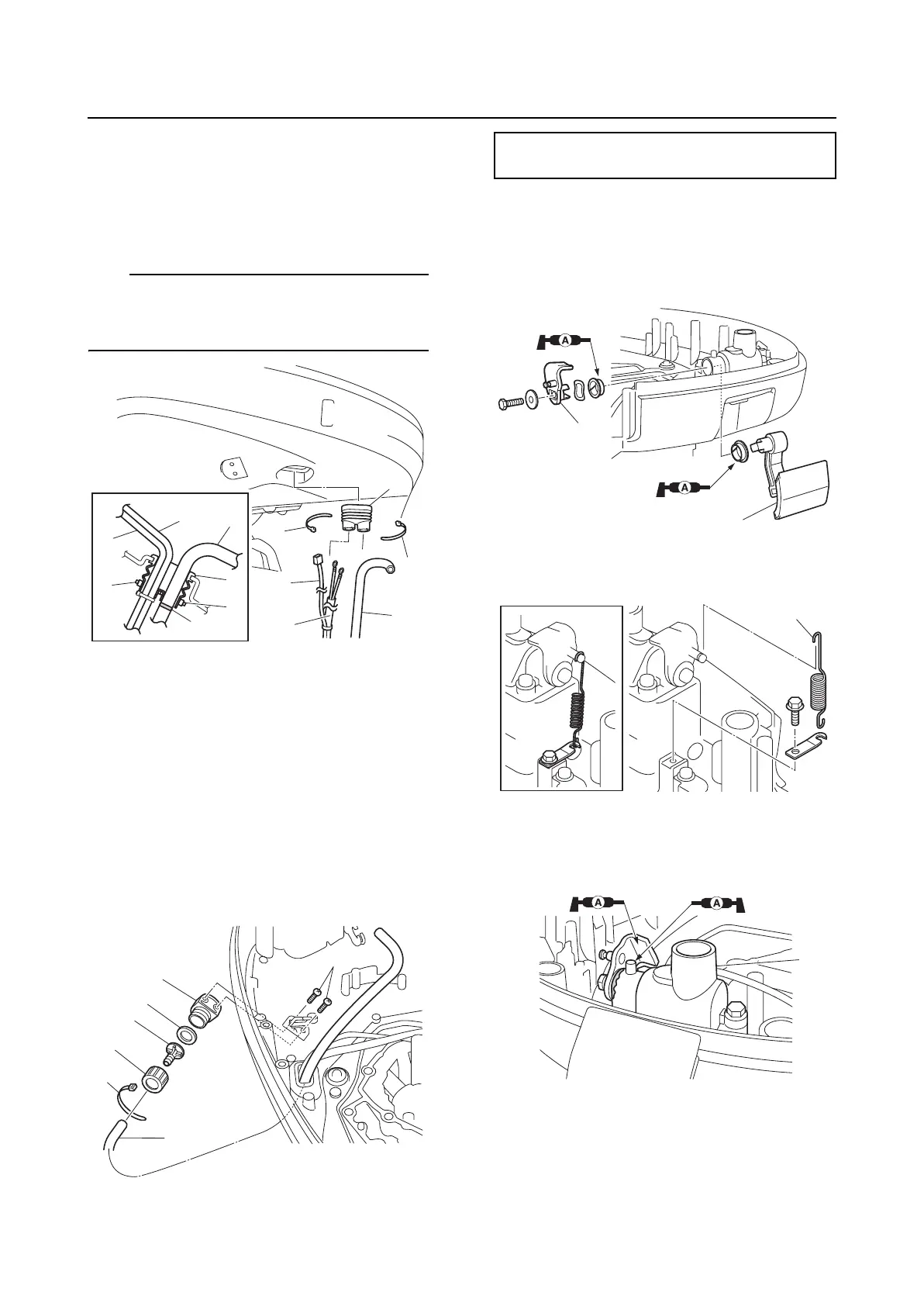
PTT switch and cowling lock lever
2. Pass the flushing hose “2”, trim sensor
lead “3”, and PTT motor leads “4”
through the grommet “1”, and then fasten
them using the plastic ties “5” around the
grommet “1”.
TIP:
Align the white paint mark “a” on the flushing
hose “2” with the outer end of the grommet
“1”.
3. Install the flushing hose adapter “1”, and
then tighten the flushing hose adapter
screws “2” to the specified torque.
4. Route the flushing hose through the hose
joint “3”, install it to the hose joint “4”, and
then fasten the flushing hose “5” using
the plastic tie “6”.
5. Install the hose joint to the adapter “1”
along with the gasket “7”.
Installing the cowling lock lever
1. Install the cowling lock lever “1” and lever
“2”.
2. Install the spring “1”.
3. Inject grease into the housing “1” until
grease comes out from the cowling lock
lever bushing.
Installing the PTT switch
1. Install the gasket “1”, PTT switch “2”, and
holder “3”.
2
2
1
1
5
5
5
5
3
3
4
4
a
1
2
4
3
5
6
7
Flushing hose adapter screw “2”:
5 N·m (0.5 kgf·m, 3.7 ft·lb)
1
2
1
1