5-20
Charging unit and component
0
1
2
3
4
5
6
7
8
9
10
A
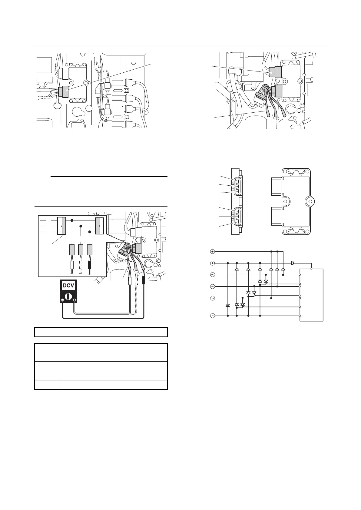
2. Connect the special service tool “1”, and
then measure the Rectifier Regulator
output voltage.
TIP:
Do not use peak voltage adapter B when
measuring the Rectifier Regulator output volt-
age.
3. Disconnect the special service tool “1”
and lighting coil coupler “a”.
4. Set the digital circuit tester to the diode
mode, and then check the Rectifier Reg-
ulator for continuity.
Test harness (3 pins) “1”: 90890-06846
Rectifier Regulator output voltage:
Red (R)–Black (B)
r/min
Loaded
1500 3500
DC V 13 13
a
R
R
RR
B
B
1
1
1
a
a
b
c
d
e
f
a
b
c
d
e
f