7-4
Power unit (check and adjustment)
4. Remove the driven sprockets, camshaft
caps, and camshafts. See “Removing the
driven sprocket and camshaft” (7-35).
5. Remove the valve lifters. See step 1 in
“Removing the cylinder head” (7-40).
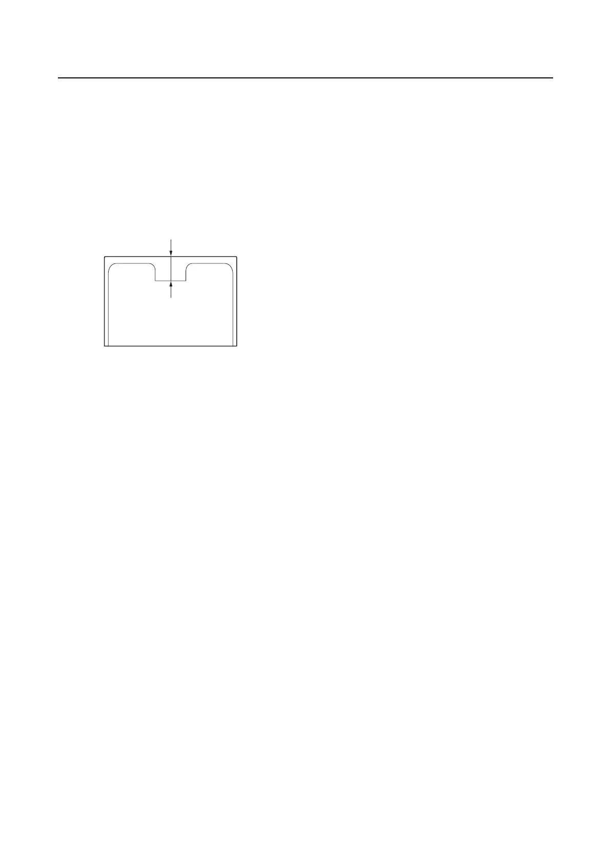
6. Measure the valve lifter thickness “a”,
and then write down the measurement
data.
7. Select the necessary valve lifter by calcu-
lating its thickness using the following for-
mula.
Calculation formula:
Necessary valve lifter thickness = Removed
valve lifter thickness + Measured valve clear-
ance – Specified valve clearance
Example:
Removed valve lifter thickness = 3.000 mm
Measured valve clearance = 0.30 mm
Specified valve clearance = 0.20 mm
Necessary valve lifter thickness
= 3.000 mm + 0.30 mm – 0.20 mm
= 3.100 mm
8. Install the selected valve lifter into the
cylinder head. See step 5 in “Installing
the cylinder head” (7-46).
9. Install the camshafts, camshaft caps, and
driven sprockets. See “Installing the
driven sprocket and camshaft” (7-36).
10. Install the timing belt. See “Installing the
timing belt” (7-18).
11. Install the stator assembly. See “Install-
ing the stator assembly” (7-14).
12. Install the flywheel magnet. See “Install-
ing the flywheel magnet” (7-15).
a