7-37
Camshaft
0
1
2
3
4
5
6
7
8
9
10
A
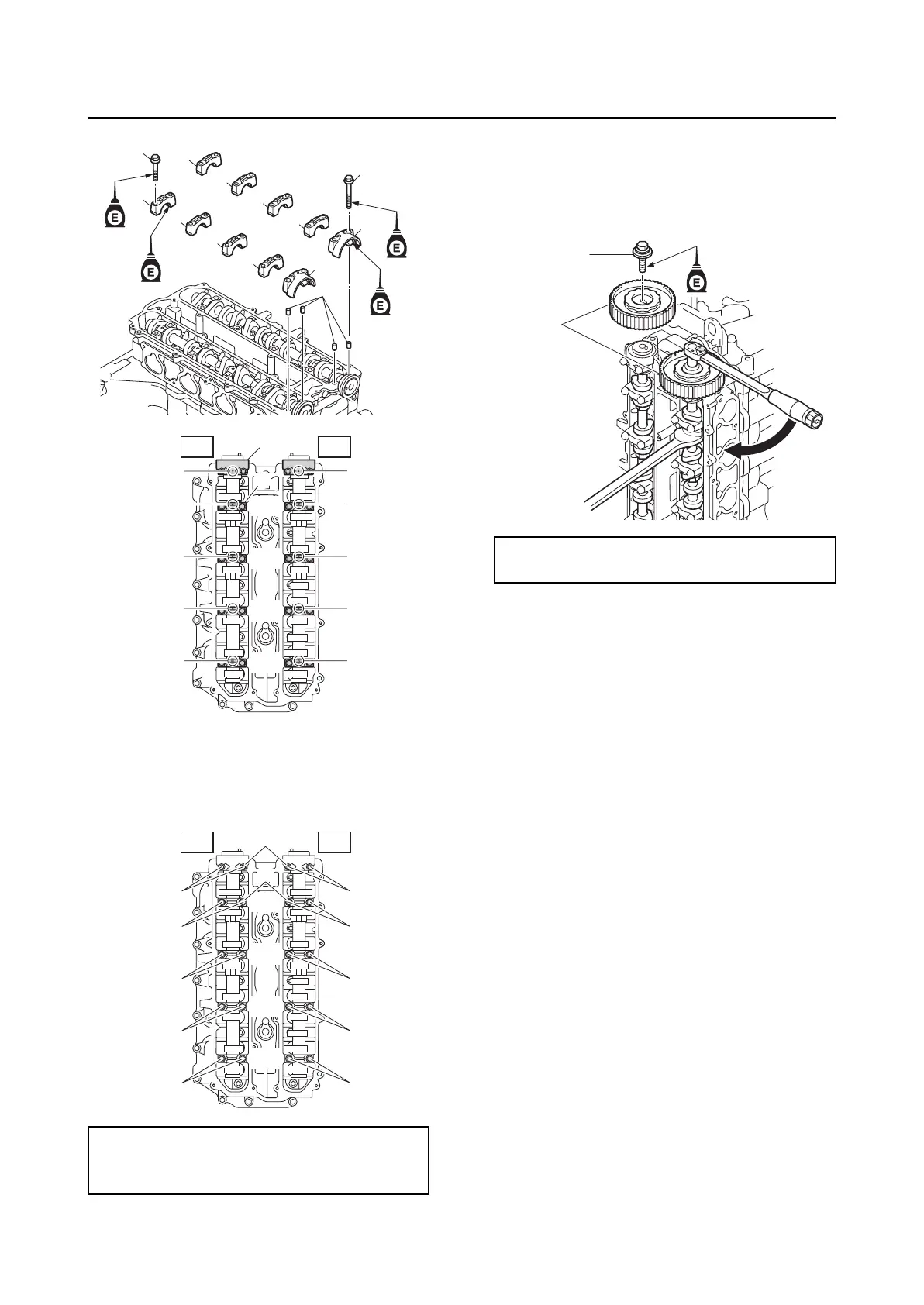
5. Tighten the camshaft cap bolts “1” and
“2” gradually to the specified torques in 2
stages and in the order [1], [2], and so
on.
6. Install the driven sprockets “1”.
7. Secure the camshaft using a wrench,
and then tighten the driven sprocket bolts
“2” to the specified torque.
8. Install the cylinder head cover. See step
11 in “Checking the valve clearance” (7-
1).
Camshaft cap bolts “4” and “5”:
1st: 9 N·m (0.9 kgf·m, 6.6 ft·lb)
2nd: 17 N·m (1.7 kgf·m, 12.5 ft·lb)
3
3
3
3
2
4
3
5
3
3
3
2
1
EX IN
#1
#2
#3
#4
1
2
3
4
5
6
7
8
9
10
2
3
EX IN
#1
#2
#3
#4
1
2
[5]
[1]
[4]
[2]
[3]
[5]
[1]
[4]
[2]
[3]
Driven sprocket bolt “2”:
60 N·m (6.0 kgf·m, 44.3 ft·lb)
1
2