9-36
PTT unit
0
1
2
3
4
5
6
7
8
9
10
A
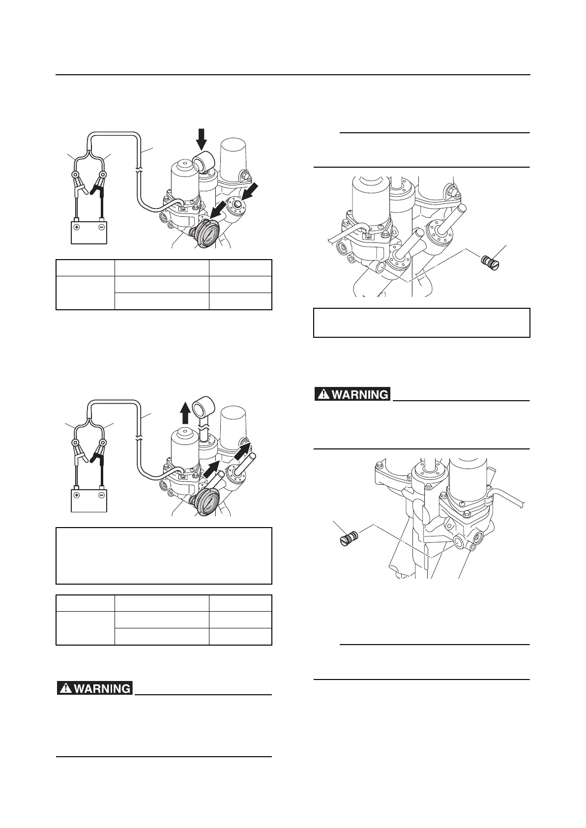
8. Connect the battery jumper leads to the
PTT motor lead “1” to fully retract the
PTT rams.
9. Reverse the connection between battery
jumper leads and the PTT motor lead “1”
to fully extend the PTT rams, and then
measure the hydraulic pressure when the
reading on the pressure gauge stabilizes.
10. Remove the special service tools.
Be careful when removing the special ser-
vice tool. Fluid could be expelled force-
fully from the PTT unit due to internal
pressure.
11. Install the main valve “1”, and then
tighten it to the specified torque.
TIP:
Install the main valve “1” quickly before any
fluid flows out of the hole.
12. Remove the main valve “1” from the
opposite side.
Be careful when removing the main valve.
Fluid could be expelled forcefully from the
PTT unit due to internal pressure.
13. Install the special service tools “1” and
“2”.
TIP:
Install the special service tools quickly before
any fluid flows out of the hole.
Ram PTT motor lead Battery
Retract
Green (G) (+)
Blue (L) (–)
Hydraulic pressure (up):
11.20–13.20 MPa
(112.0–132.0 kgf/cm
2
,
1624.0–1914.0 psi)
Ram PTT motor lead Battery
Extend
Blue (L) (+)
Green (G) (–)
L
G
1
L
G
1
Main valve “1”:
11 N·m (1.1 kgf·m, 8.1 ft·lb)
1
1