181
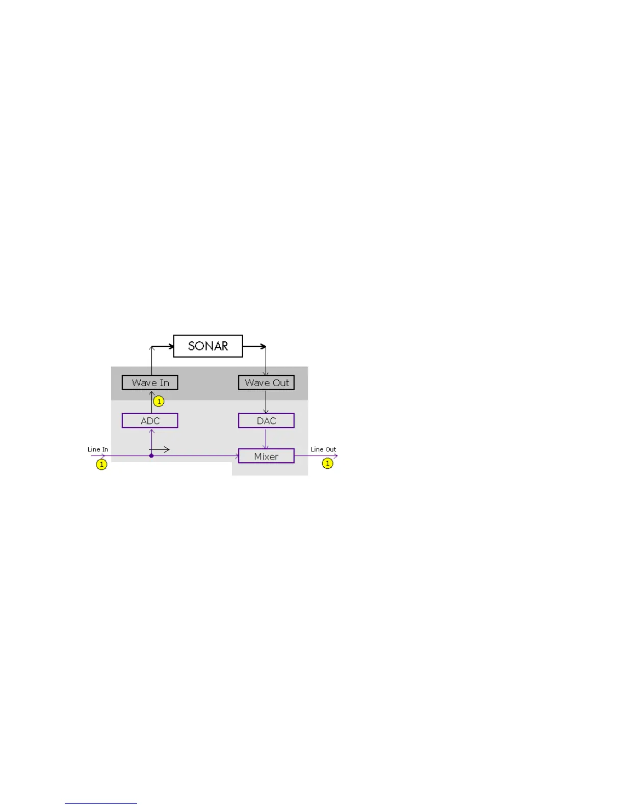
The bottom block of the picture represents the sound card. The shaded area above
it represents the audio drivers. The unshaded area at the top represents the main
environment of the operating system.
As the diagram shows, analog audio flows into the card's line input (on the left),
and is immediately split in two. One branch goes up through the analog-to-digital
converter (ADC), where the audio is digitized, buffered and fed to the driver
(labeled Wave In in the diagram).
The digital audio data buffers are read by SONAR from the Wave In driver,
processed, and then sent out to the Wave Out driver. The driver passes the digital
audio buffers through a digital-to-analog converter (DAC), where the audio data is
converted back to an analog signal.
Finally, this analog output signal is mixed with the original branch of the input
analog signal, and the summed result is presented to the sound card's line output.
With this information in hand, let's follow a simple audio signal through the
system to understand how echoes get introduced into the input monitor path.
Suppose you are counting "1, 2, 3" into your sound card very quickly. When you say
the first "1," this sound immediately appears in all the places indicated in the
illustration above. In other words, the analog audio signal is pure electrical signal
say “1”