93
M2.0-1055-100
HYDRAULIC
Accessory Clamp Set-Up
Accessory Clamp Set-Up
Attachment Setup - General
Hydraulics for optional attachments, such as carton
clamps, are controlled by the mast manifold through a
crossover relief manifold assembly mounted on the
carriage. The crossover relief manifold has an adjust-
able relief valve to regulate maximum pressure to the
attachment.
PRVA replaces RVA on the mast manifold when the
truck is equipped with the pressure regulator option.
This option allows multiple pressures to be set for the
attachment by setting the pressure regulator (PRVA)
tag pressures to desired levels through the Service
Menu.
AVOID HIGH PRESSURE FLUIDS-Escaping fluid un-
der pressure can penetrate the skin causing serious in-
jury. Relieve pressure before disconnecting hydraulic
lines. Tighten all connections before applying pres-
sure. Keep hands and body away from pin holes which
eject fluids under high pressure. Use a piece of card-
board or paper to search for leaks. Do not use your
hand.
Any fluid injected into the skin under high pressure
should be considered as a serious medical emergency
despite an initial normal appearance of the skin. There
is a delayed onset of pain, and serious tissue damage
may occur. Medical attention should be sought imme-
diately by a specialist who has had experience with this
type of injury.
Attachment Setup - Clamp
1. Set the carriage mounted crossover relief valve to
the maximum rated pressure of the attachment.
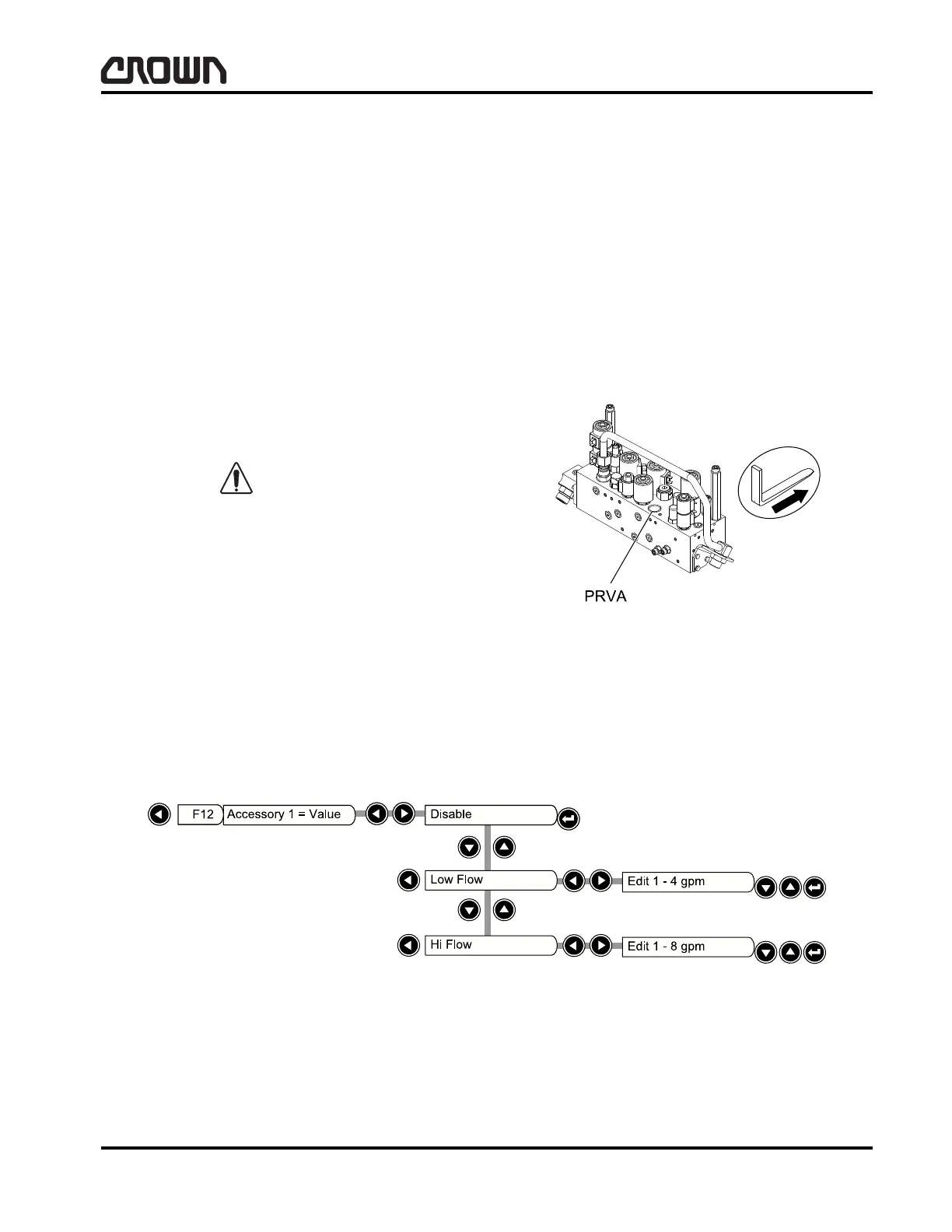
– If equipped with Electronic Pressure Regulator,
locate the accessory pressure regulator valve
(PRVA) on the mast manifold. PRVA replaces
RVA when the truck is equipped with pressure
regulator option. To disable the pressure regu-
lator option, remove the coil from PRVA, while
leaving the wires connected. Failure to leave
the wires connected will cause a fault. Refer to
Figure 15927.
– Use Service Menu, F12, to set Accessory 1, Hi
Flow, to three gpm. F12 must be set to “Hi
Flow” to enable F13 Accessory 2. Refer to
Figure 19637. For more information on Service
Menus, refer to Electrical, Access 123…Sys-
tem.
Figure 15927
Figure 19637
Crown 2008 PF17288-1
 Loading...