303
M5.0-1055-005
02 Rev. 2/09
BRAKE
Brake
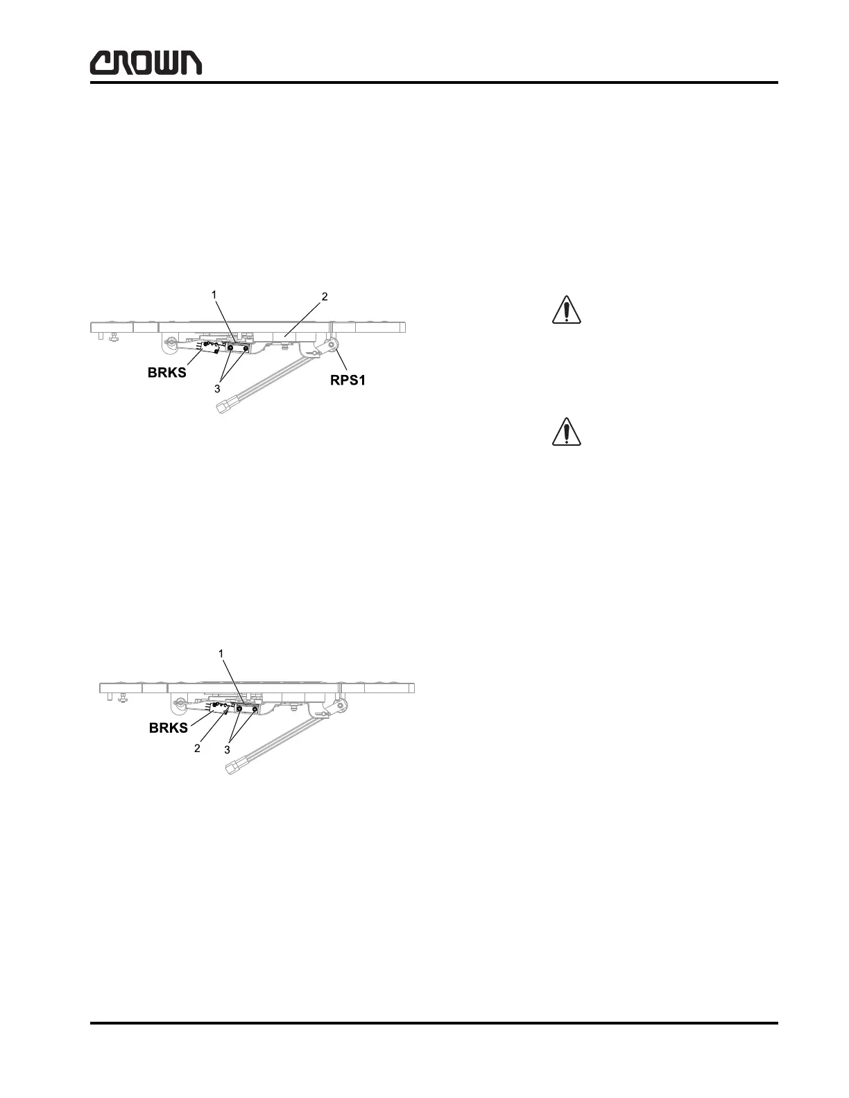
Brake Switch Adjustment (BRKS)
1. Key truck OFF, disconnect battery and chock
wheels.
2. Remove or tilt floorboard assembly up to gain ac-
cess to the brake pedal switch (BRKS).
3. Press brake pedal (2) down until it is contact with
poly stop. Refer to Figure 16028-01.
4. With the brake pedal against the poly stop, loosen
the adjustment bracket screws (3) and rotate the
adjustment bracket (1) down until the switch
reaches its maximum travel position. Refer to Fig-
ure 16029-01.
5. Tighten the adjustment bracket screws (3).
6. Verify the BRKS switch makes and breaks within
the first 20 to 30 percent travel of the brake pedal
from the fully depressed position. The parking
brakes nominally are set at 30 percent of pedal
travel. Refer to A2.3.9.2 in Service menu to review
setting.
Parking Brake Removal
Wear appropriate protective items, such as safety
glasses, whenever performing maintenance work. Do
not place fingers, hands or arms through mast or posi-
tion them at pinch points.
In this section you will be required to block the mast.
Control Of Hazardous Energy Lockout/Tagout pro-
vides information for performing the above procedures
along with some additional information on other proce-
dures dealing with truck maintenance. This section
should be read and reviewed prior to mast blocking, as
outlined in this section.
1. Move truck to an area set aside for maintenance.
2. Raise mast high enough to gain access to the park-
ing brake mounted on the end of the drive unit. Re-
fer to Control Of Hazardous Energy Lockout/Ta-
gout, Blocking Mast and Lifting Mechanism of the
Service and Parts Manual for correct mast blocking
procedures.
3. Securely block the mast, key truck OFF, and dis-
connect battery.
LH Brake = P/N 136830 (4 internal springs)
RH Brake = P/N 136802 (8 internal springs)
4. Disconnect either CA435 (LH brake) or CA436 (RH
brake).
Figure 16028-01
1 Adjuster Bracket
2 Brake Pedal Fully Depressed Contacting Poly Stop
3Screws
Figure 16029-01
1 Rotate Adjuster Bracket Down
2 Switch at Maximum Travel Position
3 Tighten Screws after Adjustment is Complete
Crown 2007 PF15692-5 Rev. 2/09
 Loading...