197
M4.3-1055-500
ELECTRICAL
Control Modules
Control Modules
Traction Drive Module
Basics of System Operation
The AC traction drive module (Access 3) applies a vari-
able frequency current and pulse width modulated
three phase AC voltage to the motor stator to generate
a rotating magnetic field. The rotating magnetic field
induces an opposing magnetic field in the rotor which
causes the rotor to turn. Using this technology elimi-
nates the need for motor brushes as well as forward
and reversing contactors and the associated mainte-
nance. The traction drive module contains the power
circuitry for converting the DC input to three phase AC
output and controls the Pulse Width Modulation (PWM)
of the voltage and the frequency of the resultant current
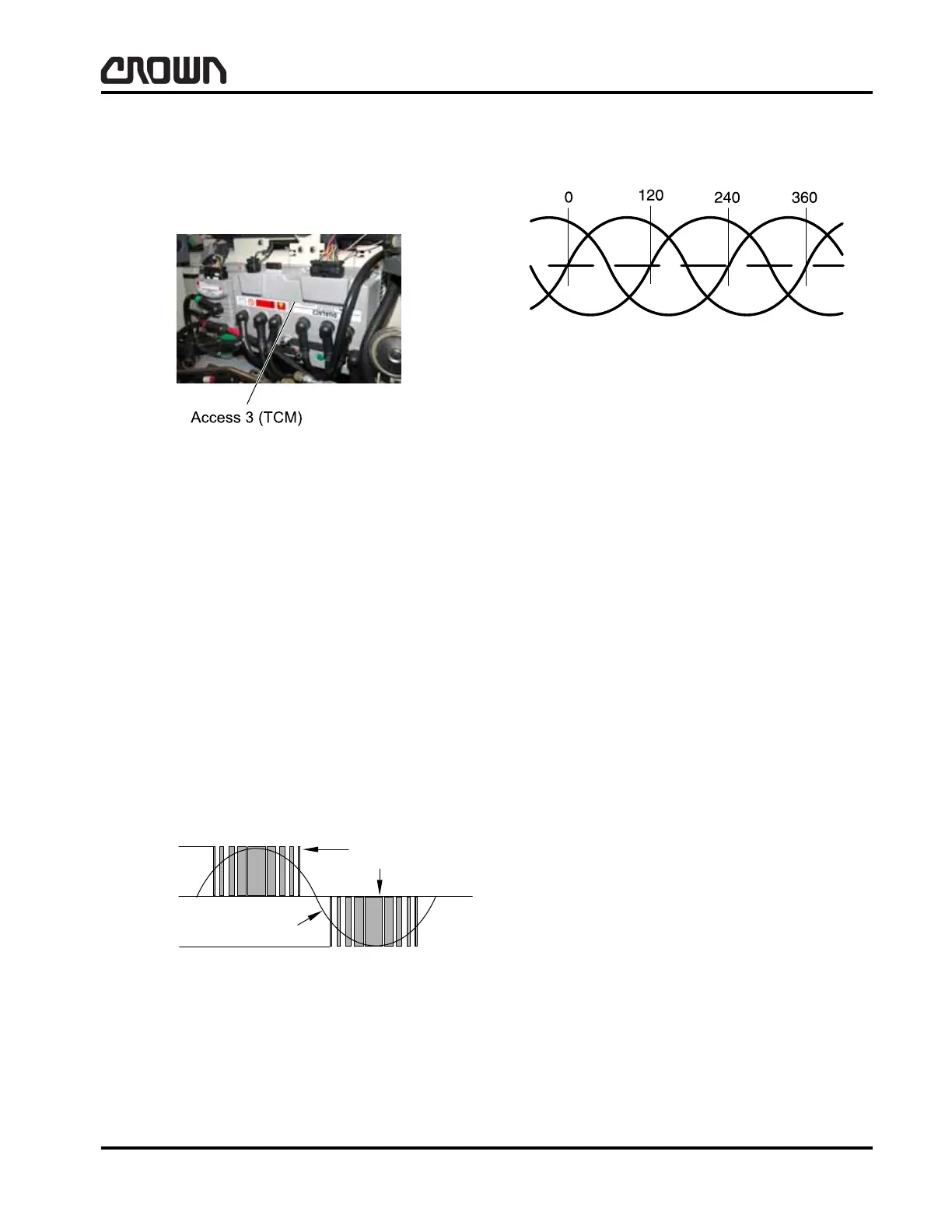
waveform. The resulting output is shown (single phase
shown).
Each phase of the output is 120 degrees out of phase
as shown.
Each phase is applied to separate windings in the
motor stator, resulting in the rotating magnetic field
which causes rotation of the rotor. Access 3 manages
the speed regulation and various system inputs and
outputs.
Inherent to the design of AC motors is generated volt-
age when using motor braking. Without the need for
additional contactors or resistance, this voltage is
applied to the battery to extend the usable charge
available.
Motor torque is variable making closed loop speed reg-
ulation possible. This will maintain vehicle speed,
within the limits of the motor and drive system, as
determined by the speed request. A speed sensor
bearing in the motor provides the feedback signal to
the traction drive module for control of the AC power
converter. Speed feedback is also provided to Access
3 for speed regulation.
Control Circuit Operation
The control circuitry of the Access 3 module is software
driven with the parameters set for the system by the
Features and Performance menus.
Figure 15950
Figure 9892-01
Positive
Battery
Volts
Negative
Battery
Volts
Current
Waveform
Voltage
Modulation
Figure 9893
Crown 2007 PF15712-1
 Loading...