CYLINDERS
Cylinders
350
M8.0-1055-004
01 Rev. 6/08
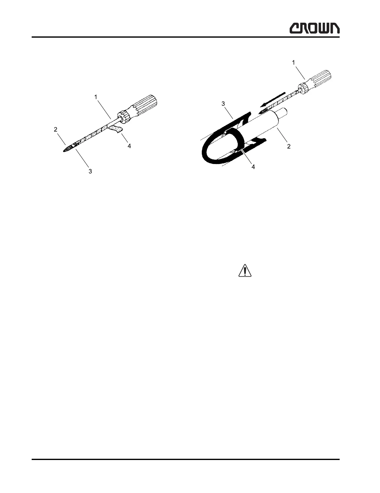
4. The packing is located below the cap and remains
in the cylinder bore after the cap is removed. A pair
of special tools can be used to facilitate packing
removal (refer to Figure 15963).
To make these tools, weld or braze a headless 4.0 mm
self-tapping (No. 8 metal) screw to the end of a screw-
driver. The screwdriver must have at least 150 mm
(6.0 in) of shank length with no larger than 4.0 mm
(0.156 in) shank diameter. After attaching the screw to
the screwdriver, grind off excess weld to a diameter of
4.0 mm (0.156 in). Wrap the shank with electrical tape
from the tip of the screw to the screwdriver handle. This
will prevent scratching of the cylinder bore or the ram.
Extreme care should be taken to prevent damage to
cylinder wall and ram assembly.
5. Insert the tools between the ram and the cylinder
walls, 180° apart, and screw into the face of the
packing (refer to Figure 15964).
6. After the threads are sufficiently secured into the
packing, evenly pull on the screwdriver handles
until the packing is removed.
Close inspection of seal seating critical areas should
be made before the new seal is installed.
Figure 15963
1 Screwdriver 152 mm (6 in) Shaft Length (Min.) 4 mm
(0.156 in) Shaft Diameter (Max.)
2 No. 8 Metal Screw Headless (4 mm Self-Tapping)
3 Weld (Grind Off Excess) to a Max. Dia. of 4 mm
(0.156 in)
4 Tape
Figure 15964
1 Seal Pulling Tool
2Ram
3 Cylinder Tube
4 Seal
Crown 2007 PF15682-4 Rev. 6/08
 Loading...