CHAPTER 31
Replacing QFX5100 Components
IN THIS CHAPTER
Installing and Removing QFX5100 Device Hardware Components | 429
Installing a Power Supply in a QFX5100 Device | 430
Removing a Power Supply from a QFX5100 Device | 432
Installing an Expansion Module in a QFX5100 Device | 434
Removing an Expansion Module from a QFX5100 Device | 438
Installing a Fan Module in a QFX5100 Device | 440
Removing a Fan Module from a QFX5100 Device | 442
Installing and Removing QFX5100 Device Hardware Components
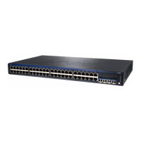
The QFX5100 switch chassis is a rigid sheet-metal structure that houses the hardware components. The
field-replaceable units (FRUs) in QFX5100 devices are:
•
Power supply
•
Fan module
•
Expansion module (QFX5100-24Q and QFX5100-24Q-AA only)
•
SFP+ transceiver
•
QSFP+ transceiver
All of the QFX5100 device FRUs are hot-insertable and hot-removable: you can remove and replace them
without powering off the switch or disrupting switch functions.
CAUTION: Replace a failed power supply with a new power supply within 1 minute
of removal to prevent chassis overheating. Replace a failed fan module with a new fan
within 1 minute of removal to prevent chassis overheating.
429

 Loading...


