As shown in Table 83 on page 511, there are four bi-color LEDs for each QSFP+ port. The first LED is used
and the remaining LEDs are not used when the interface is configured for 40-Gigabit Ethernet and connected
to a QSFP+ transceiver. All four LEDs are used when the interface is configured for 10-Gigabit Ethernet
and the port is connected using an optical split cable or a copper DACBO cable. Table 85 on page 513
describes how to interpret the QSFP+ LEDs.
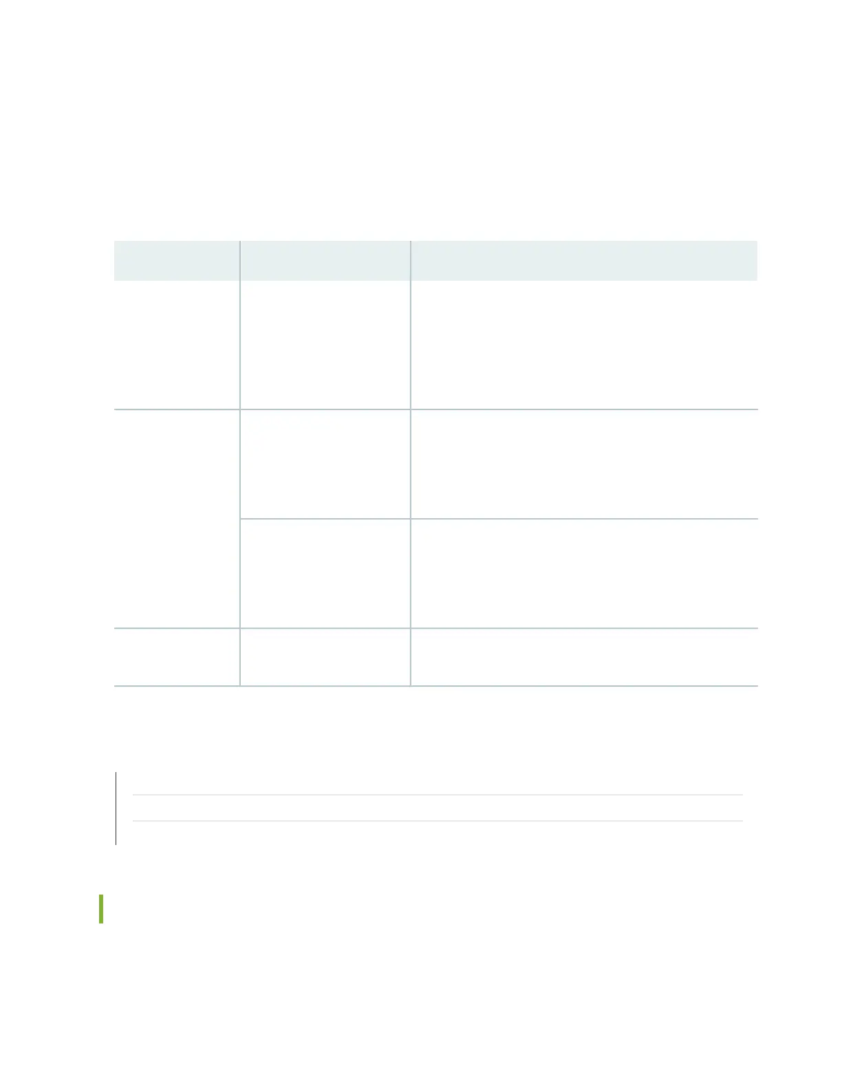
Table 85: Network Port LEDs on QSFP+ Ports on a QFX5100 Switch
DescriptionStateColor
The port is administratively disabled, there is no power, the
link is down, or there is a fault.
NOTE: When configured for 10-Gigabit Ethernet, the LED
remains unlit only if all four of the 10-Gigabit Ethernet SFP+
breakout links are down.
OffUnlit
A link is established, but there is no link activity.
NOTE: When configured for 10-Gigabit Ethernet, the LED is
lit green when at least one of the four 10-Gigabit Ethernet
SFP+ breakout links is established.
On steadilyGreen
A link is established, and there is link activity.
NOTE: When configured for 10-Gigabit Ethernet, the LED is
lit green when at least one of the four 10-Gigabit Ethernet
SFP+ breakout links is established.
Blinking
All four LEDs blink to indicate the beacon function was enabled
on the port.
BlinkingAmber
RELATED DOCUMENTATION
Management Panel of a QFX5100 Device
Installing a Transceiver in a QFX Series Device | 481
Connecting a Fiber-Optic Cable to a QFX Series Device | 488
Fan Module LED on a QFX5100 Device
Figure 188 on page 514 shows the location of the LED next to the fan module.
513

 Loading...


