EasyManuals Logo

Juniper QFX5110 Series User Manual

Juniper QFX5110 Series
669 pages
To Next Page IconTo Next Page
To Previous Page IconTo Previous Page
Page #549 background imageLoading...
Page #549 background image
DC Power Supply LEDs on a QFX3500, QFX3600, or QFX3600-I Device
Figure 196 on page 525 shows the location of the LEDs on the DC power supply.
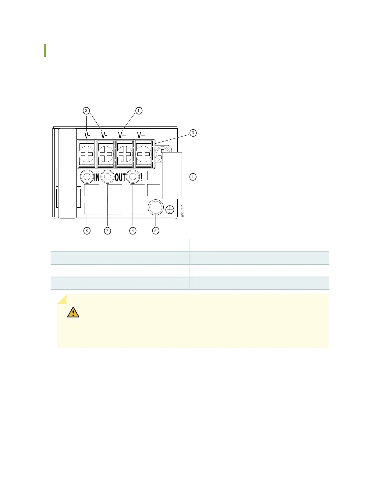
Figure 196: DC Power Supply Faceplate on a QFX3500, QFX3600, or QFX3600-I Device
g050211
1
678
5
2
3
4
51 ESD grounding pointShunt positive input terminals
62 Fault LEDShunt negative input terminals
73 Output LEDTerminal block
84 Input LEDEjector lever
CAUTION: The V+ terminals are shunted internally together, as are the V- terminals.
The same polarity terminal can be wired together from the same source to provide an
additional current path in a higher power chassis. Do not connect the terminals to
different sources.
Table 95 on page 526 describes the LEDs on the DC power supplies.
525

Table of Contents

Questions and Answers:

Question and Answer IconNeed help?

Do you have a question about the Juniper QFX5110 Series and is the answer not in the manual?

Juniper QFX5110 Series Specifications

General IconGeneral
Rack Units1U
Operating SystemJunos OS
Form FactorFixed
ManagementCLI, SNMP, NETCONF
Operating Temperature32°F to 104°F (0°C to 40°C)
Storage Temperature-40°F to 158°F (-40°C to 70°C)
Humidity5% to 90% non-condensing
AC Power Input100-240 VAC
Power SupplyRedundant, hot-swappable

Related product manuals