VCP connections. See “Connecting a QFX5100 Device in a Virtual Chassis Fabric” on page 295 for a cabling
diagram.
BEST PRACTICE: Whenever possible use the QFX5100-24Q device as a spine device. By using
the QFX5100-24Q device in a maximum configuration of 20 total devices, four QFX5100-24Q
devices may be used as spine devices. All members can be connected to the spine using QSFP+
ports.
As of Junos OS release 17.3R1, you can also connect a QFX5100-24Q as a leaf device in a QFX5110 VCF
or as a member in a QFX5110 Virtual Chassis.
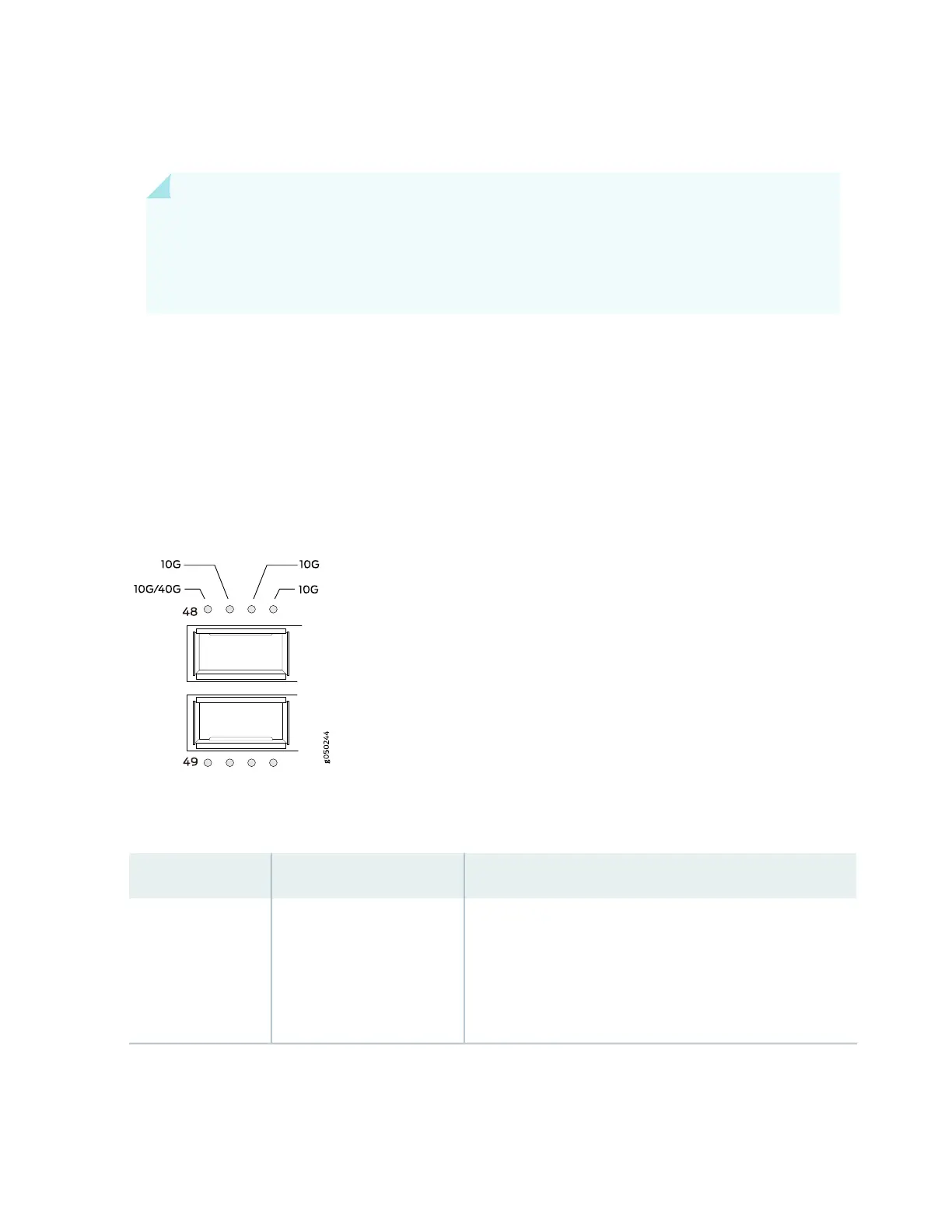
Port LEDs
The bi-color LEDs labeled Link/Activity LED in Figure 17 on page 35 indicate link activity or faults.
Figure 17: LEDs on the QSFP+ Uplink Ports
Table 3 on page 35 describes the SFP+ access port LEDs.
Table 3: Port LEDs on a QFX5100-24Q Switch
DescriptionStateColor
The port is administratively disabled, there is no power, or there
is a fault.
NOTE: When configured for channelized 10-Gigabit Ethernet,
the LED remains unlit only if all four of the 10-Gigabit Ethernet
SFP+ breakout links are down.
OffUnlit
35

 Loading...


