CHAPTER 38
Viewing QFX5100 System Information
IN THIS CHAPTER
Chassis Status LEDs on a QFX5100 Device | 505
Management Port LEDs on a QFX5100 Device | 508
Access Port and Uplink Port LEDs on a QFX5100 Device | 510
Fan Module LED on a QFX5100 Device | 513
AC Power Supply LEDs on a QFX5100 Device | 514
DC Power Supply LEDs on a QFX5100 Device | 516
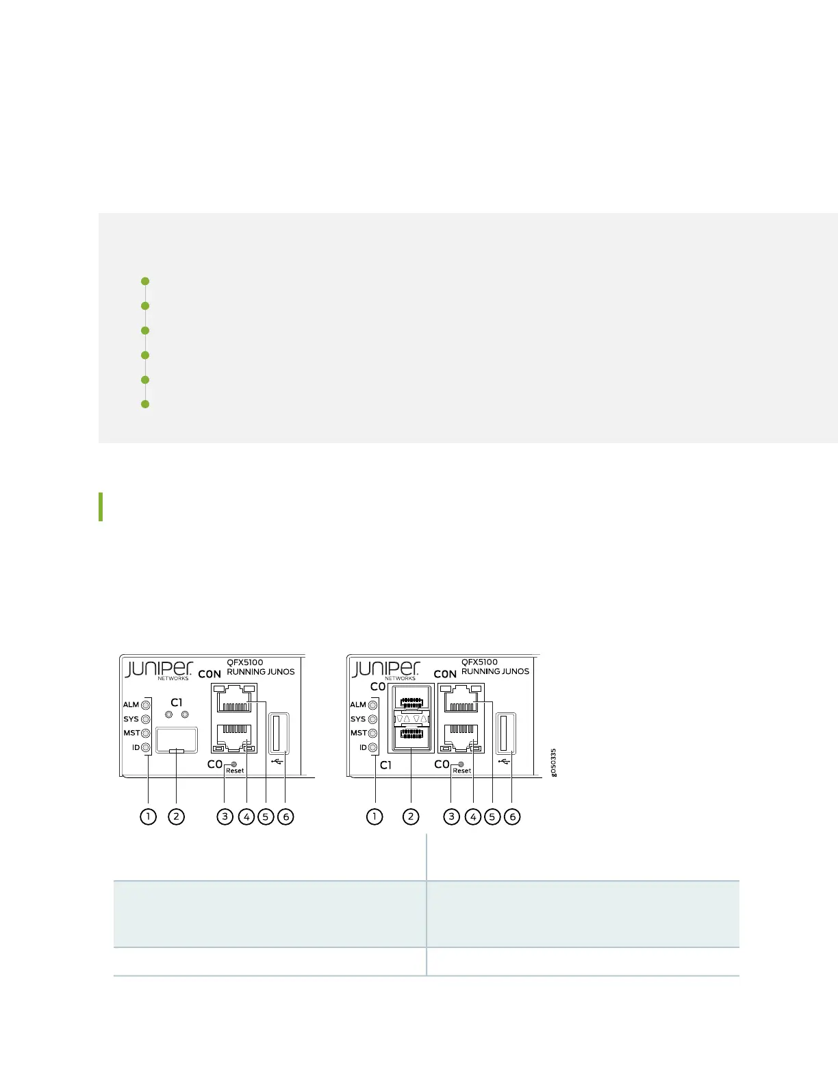
Chassis Status LEDs on a QFX5100 Device
The QFX5100 switch series has four status LEDs on the FRU side of the chassis, next to the management
ports (see Figure 186 on page 505).
Figure 186: Chassis Status LEDs on a QFX5100 Switch
4—1— em0–RJ-45 (10/100/1000 Base-T) management
Ethernet port (C0)
Status LEDs
5—2— RJ-45 console port (CON )em1–SFP management Ethernet port (C1)
Cage (socket for either 10/100/1000 Base-T RJ45
SFP or 1GbE fiber SFP)
6—3— USB portReset button, see caution statement below
505

 Loading...


