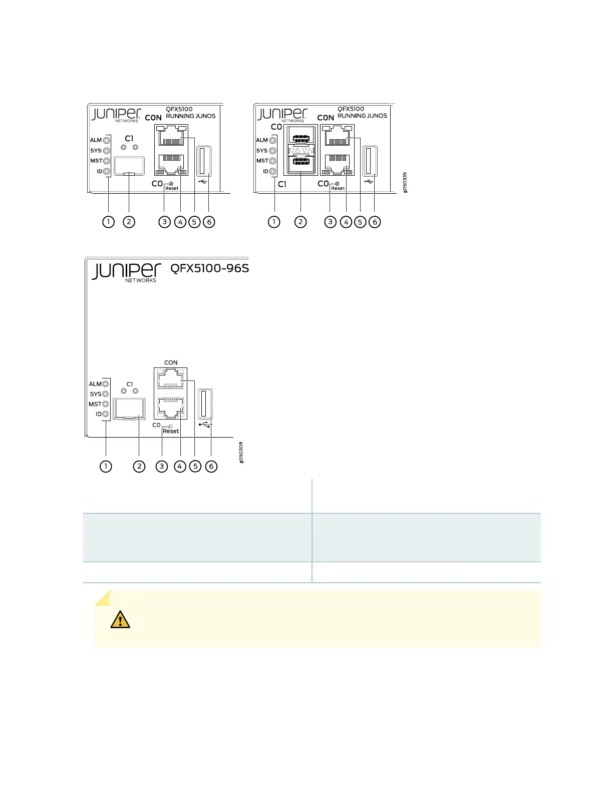
Figure 187: Management Port LEDs on a QFX5100 Switch
4—1— em0–RJ-45 (10/100/1000 Base-T) management
Ethernet port (C0)
Status LEDs
5—2— RJ-45 console port (CON)em1–SFP management Ethernet port (C1)
Cage (socket for either 10/100/1000 Base-T RJ45
SFP or 1GbE fiber SFP)
6—3— USB portReset button, see caution statement below
CAUTION: Do not use the Reset button to restart the power sequence unless under
the direction of Juniper Networks Technical Assistance Center (JTAC).
Table 82 on page 510 describes the management port LEDs.
509

 Loading...


