TOS93 Series User’s Manual 235
External Control
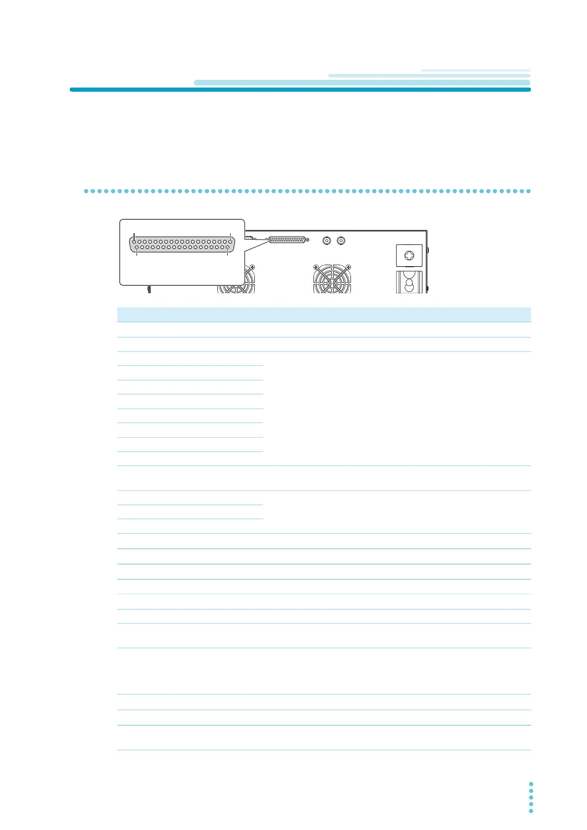
SIGNAL I/O Connector
Before using the SIGNAL I/O connector for external control, check the connector specifications, and
connect the external device to the SIGNAL I/O connector.
Pin arrangement
Pin no. IN/OUT Signal name Description See
1
IN INTERLOCK+ Activate/release interlock.
p.239
2
– COM Circuit common (chassis potential) shared by input and output. –
3
IN PM0 Select setup memories and auto test program memories.
p.241
4
IN PM1
5
IN PM2
6
IN PM3
7
IN PM4
8
IN PM5
9
IN PM6
10
IN PM7
11
IN STB Recall setup memories and programs selected with the PM0 to
PM7 signals.
p.241
12
– Reserved Not used. –
13
– Reserved
14
– Reserved
15
IN START Start a test.
p.242
16
IN STOP Stop a test.
p.242
17
IN ENABLE Enable the START signal.
p.242
18
– COM I/O circuit common (chassis potential). –
19
IN INTERLOCK- Activate/release interlock.
p.239
20
– COM I/O circuit common (chassis potential). –
21
– +24V +24 V internal power supply output terminal. Maximum output
current 100 mA.
–
22
OUT H.V ON/LINE ON Set to on in any of the following conditions.
Testing. Auto testing. Voltage remaining across the output
terminals. Power being supplied to the EUT from the
TOS9303LC through AC LINE OUT.
–
23
OUT RISE Set to on when the voltage is rising
p.243
24
OUT TEST Set to on during test time
p.243
25
OUT PASS Set to on for the duration of time specified by Pass Hold when
a PASS judgment is made.
p.244
19
20
1
37
EXT CONT connector pin number
TOS9300 example
is the same on all models.)