236 User’s Manual TOS93 Series
External Control | SIGNAL I/O Connector
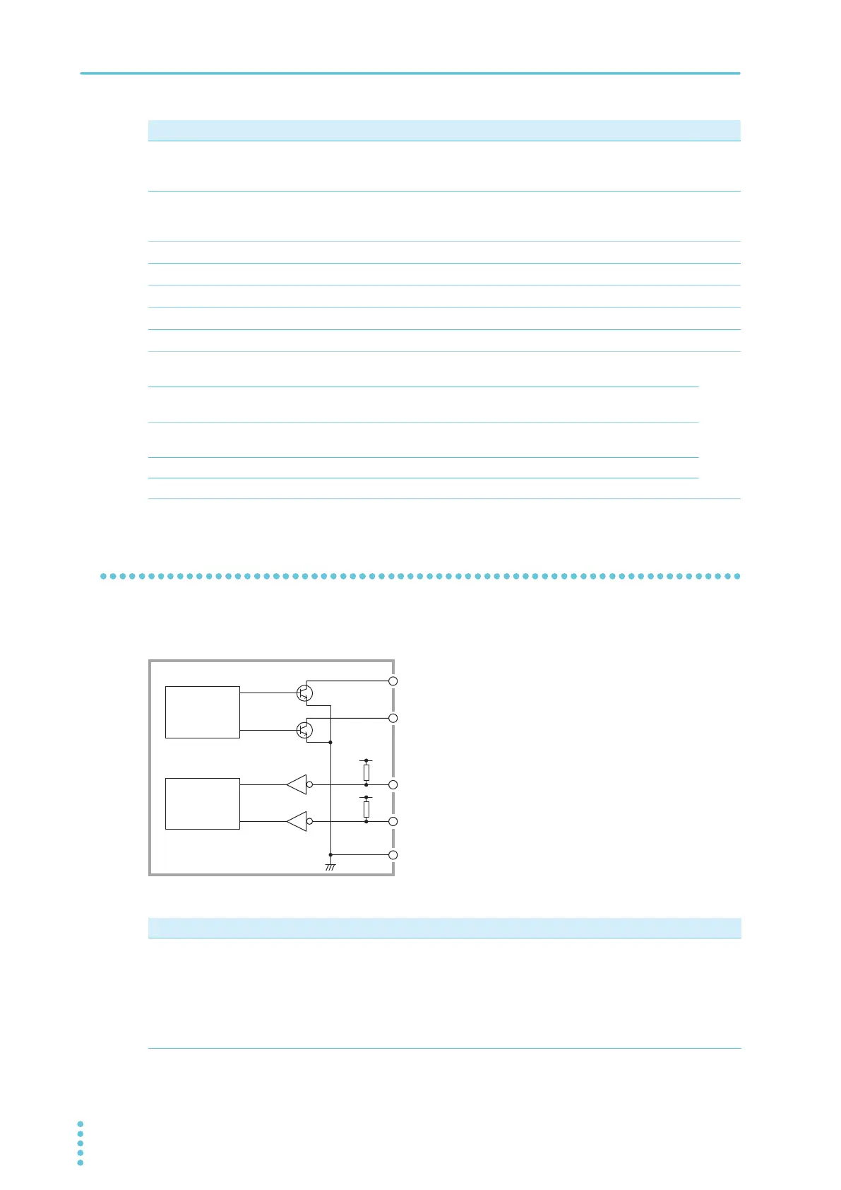
I/O signal circuit
The input signal circuit and the output signal circuit share the same common. The input terminal is pulled
up to +12 V by a resistor.
26
OUT U FAIL Set to on continuously when a Upper-FAIL judgment is made.
Or set to on continuously along with the L FAIL signal when
Contact-FAIL judgment is made.
p.244
27
OUT L FAIL Set to on continuously when an Lower-FAIL judgment is made.
Or set to on continuously along with the U FAIL signal when
Contact-FAIL judgment is made.
p.244
28
OUT PD Set to on when the test mode is set to partial discharge test.
p.243
29
OUT READY Set to on when the product is ready to start a test.
p.243
30
OUT PROTECTION Set to on when a protection function is activated.
p.23
31
OUT STEP END Set to on when each step ends during an auto test.
p.245
32
OUT CYCLE END Set to on when the last step ends during an auto test.
p.245
33
OUT ACW Set to on when the test mode is set to AC withstanding voltage
test.
p.243
34
OUT DCW Set to on when the test mode is set to DC withstanding voltage
test.
35
OUT IR Set to on when the test mode is set to insulation resistance
test.
36
OUT EC Set to on when the test mode is set to earth continuity test.
37
OUT LC Set to on when the test mode is set to leakage current test.
Pin no. IN/OUT Signal name Description See
Input signal Output signal
Opening the input terminals is equivalent to high-level input.
• Low-active control
• High-level input voltage: 11 V to 15 V
• Low-level input voltage: 0 V to 4 V
• Low-level input current: -5 mA max.
• Input time width: 5 ms min.
• Open collector output
• Output withstanding voltage: 30 Vdc
• Output saturation voltage: Approx. 1.1 V (25°C)
• Maximum output current 400 mA (TOTAL)
•
•
•
•
•
•
Output signal
controller
Input signal
controller
COM
Output signal 1
Output signal 2
Input signal 1
Input signal 2
+12 V
+12 V
Internal construction of the