34 User’s Manual TOS93 Series
Installation
Connection for Earth Continuity Tests
Applicable models: , ,
Four-terminal wiring and two-terminal wiring
There are two methods for wiring test leads to this product. They are the four-terminal wiring and two-
terminal wiring. Each method requires the test leads to be connected to different locations.
If you use the supplied test leads for earth continuity testing (TL13-TOS),
four-terminal wiring is used.
When four-terminal wiring is not possible such as when using test leads other than those supplied with the
product, two-terminal wiring is used. After making the connections, set the test conditions by referring to
“Terminal wiring method (Terminals Wire)” (p
.97).
If you use test leads other than those supplied with the product, the product specifications may not be met.
Contact your Kiku
sui agent or distributor for details.
9303
• The TOS9302, TOS9303, and TOS9303LC produce large current up to 42
A. Connect
the test leads securely. If the connection is loose, the OUTPUT terminals or the EUT
may overheat and may cause burns or injury.
• Do not connect the supplied test leads or the voltage measurement cable (the
thinner cable) of the optional test probe to the OUTPUT
terminals. Because the
nominal cross-sectional area for running the current is insufficient, they may burn
out.
CAUTION
Because the TOS9302, TOS9303, and TOS9303LC produce large current, a strong
magnetic field is created. Do not bring objects that are easily affected by magnetic fields
close to the test leads or the current output cable.
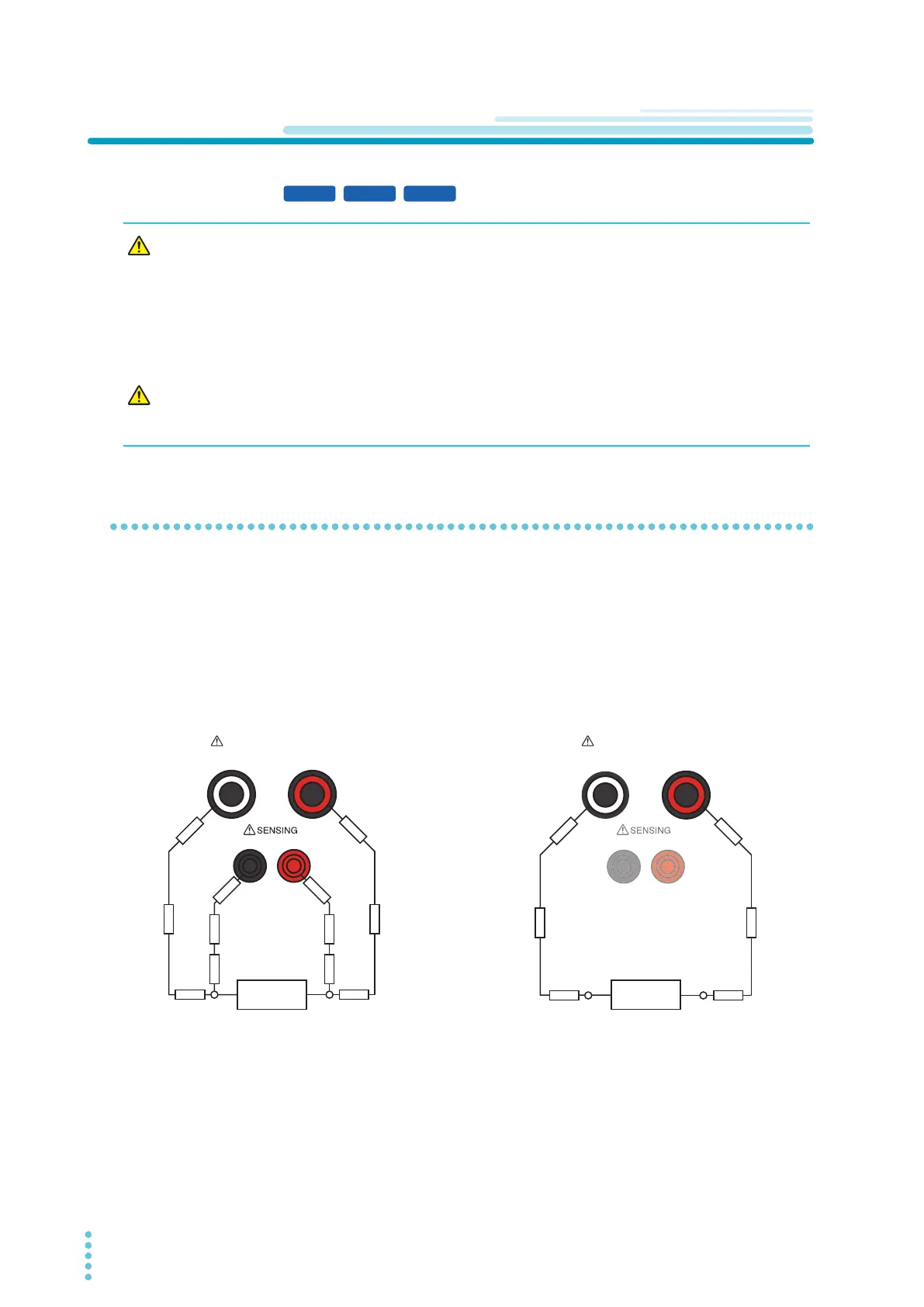
r1 to r8: Contact resistance
R1 to R4: Lead wire resistance
Four-terminal wiring
Connect test leads to the OUTPUT LO and
HI terminals and the SENSING LO and HI
terminals. The voltage across A and B can
be sampled with the SENSING terminals.
The measurement is not affected by
contact resistance r1 to r8 or the lead wire
resistance R1 to R4.
Two-terminal wiring
Connect test leads to the OUTPUT LO and
HI terminals. The sum of contact resis-
tance r1 to r4, lead wire resistance R1 and
R2, and the resistance across A and B is
measured.
r3
r5
r6
r7 r8
r4
r2r1
R2R1
R3 R4
AB
LO
OUTPUT
HI
LO HI
EARTH CONTINUITY
r3 r4
r2r1
R2R1
AB
L
LO HI
EARTH CONTINUITY
EUT EUT