TOS93 Series User’s Manual 39
Installation | Connection for Partial Discharge Tests
3
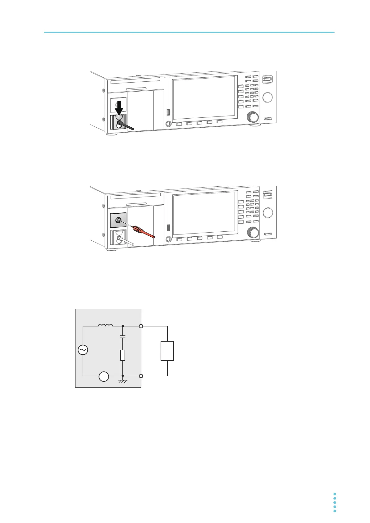
Lower the cable lock.
Check that the connection is secure.
4
Connect the low-voltage test lead (black) to the EUT.
5
Connect the high-voltage test lead (red) to the EUT.
6
Connect the high-voltage test lead (red) to the HIGH VOLTAGE terminal.
This completes the connections.
Connection diagram for PD tests
The connection diagram for PD tests is shown below.
A
Ck: Coupling capacitor
Z
m: Measurement impedance
Z: Filter (blocking coil)
TOS9301PD
HIGH VOLTAGE
LOW
EUT
Z
Ck
Zm