Parts catalog 7-5
4062-XXX
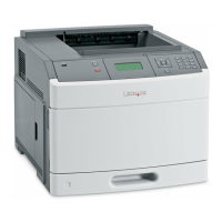
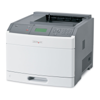
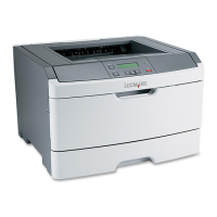
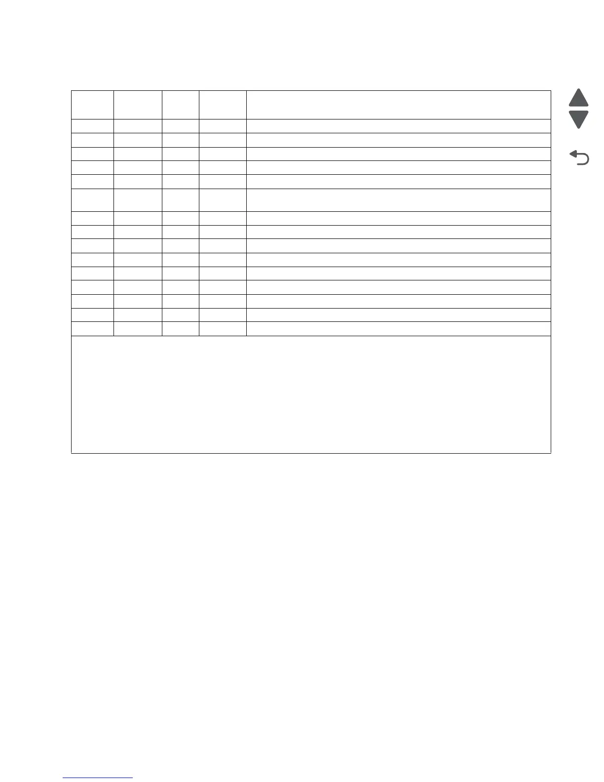
Assembly 2: T650, T652, and T654 Operator panel
Asm-
Index
Part
number
Units/
mach
Units/ kit
or pkg
Description
1 40X4366 1 1 Operator panel cable assembly (T650, T652, and T654)
2 40X4462 1 1 Operator panel door assembly (T650, T652, and T654)
3 40X4380 2 1 Counterbalance spring (T650, T652, and T654)
4 40X4397 1 1 Operator panel hinge assembly, right (T650, T652, and T654)
5 40X4616 1 1 Operator panel latch assembly (T650, T652, and T654)
6 40X4396 1 1 Operator panel hinge assembly with interlock switch, left (T650, T652, and
T654)
7 40X4415 1 1 LCD screen bezel (T650n)
7 40X4494 1 1 LCD screen bezel (T652n)
7 40X4471 1 1 LCD screen bezel (T652dn)
7 40X4628 1 1 LCD screen bezel (T654n)
7 40X4627 1 1 LCD screen bezel (T654dn)
7 40X7043 1 1 LCD screen bezel (TG654dn)
8 40X5746 1 1 Operator panel bezel, left
8 40X5729 1 1 Operator panel bezel, left (NON USB)
9 40X4377 1 1 USB cable assembly (T650, T652, and T654)
Warning: When replacing any of the following components:
• Operator panel assembly
• System card assembly
Only replace one component at a time. Replace the required component and perform a POR before replacing a second
component listed above. If this procedure is not followed, the printer will be rendered inoperable. Never replace two or
more of the components listed above without a POR after installing each one or the printer will be rendered inoperable.
Never install and remove components listed above as a method of troubleshooting components. Once a component has
been installed in a machine, it can not be used in another machine. It must be returned to the manufacturer.
 Loading...