214323 124 Revision B
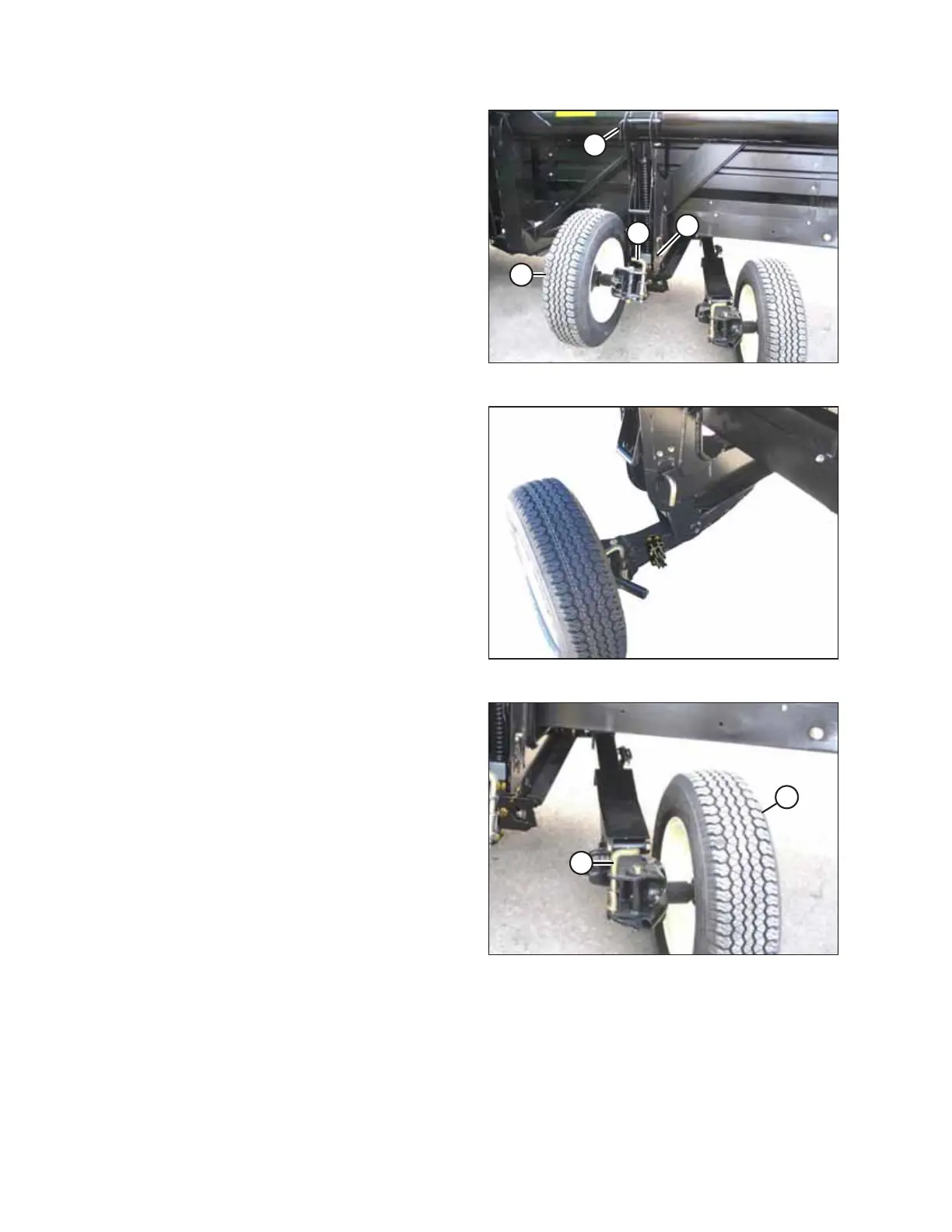
Figure 3.163: Wheel Position
6. Remove pin (A) and reinstall it at location (B). Turn the pin
to lock the linkage.
7. Pull spring pin (D) upward, swivel left wheel (C)
counterclockwise 90°, and the release the spring pin to lock
the wheel in place.
Figure 3.164: Left Wheel in Transport Position
8. Ensure the left wheel is in the transport position as shown.
Figure 3.165: Right Rear Wheel
9. Pull pin (A) and swivel right rear wheel (B) clockwise 90°.
OPERATION