214323 155 Revision B
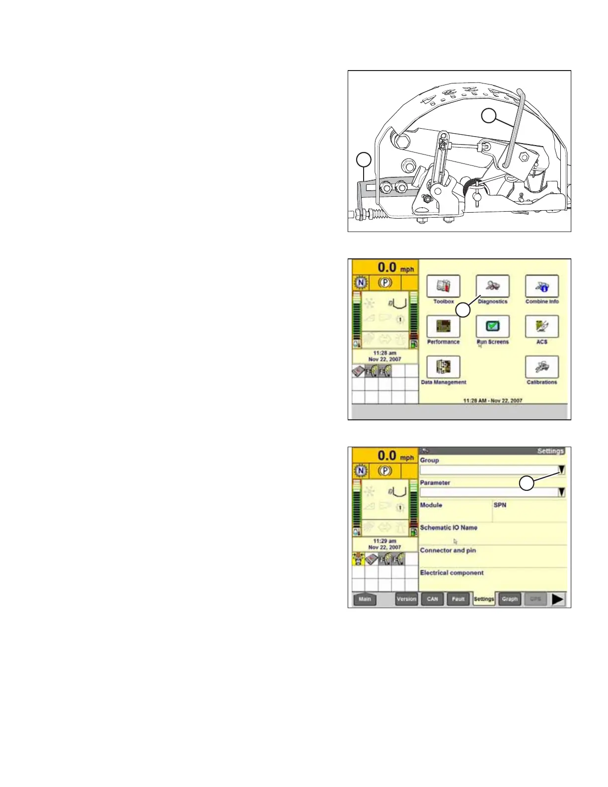
Figure 4.50: Float Indicator Box
3. Adjust cable take-up bracket (B) (if necessary) until
pointer (A) on the float indicator is on 0.
4. Ensure that the header float is unlocked.
Figure 4.51: Case IH Combine Display
5. Select DIAGNOSTICS (A) on the MAIN page. The
DIAGNOSTICS page appears.
6. Select SETTINGS. The SETTINGS page appears.
Figure 4.52: Case IH Combine Display
7. Select GROUP drop-down arrow (A). The GROUP dialog box
appears.
AUTO HEADER HEIGHT CONTROL