214323 331 Revision B
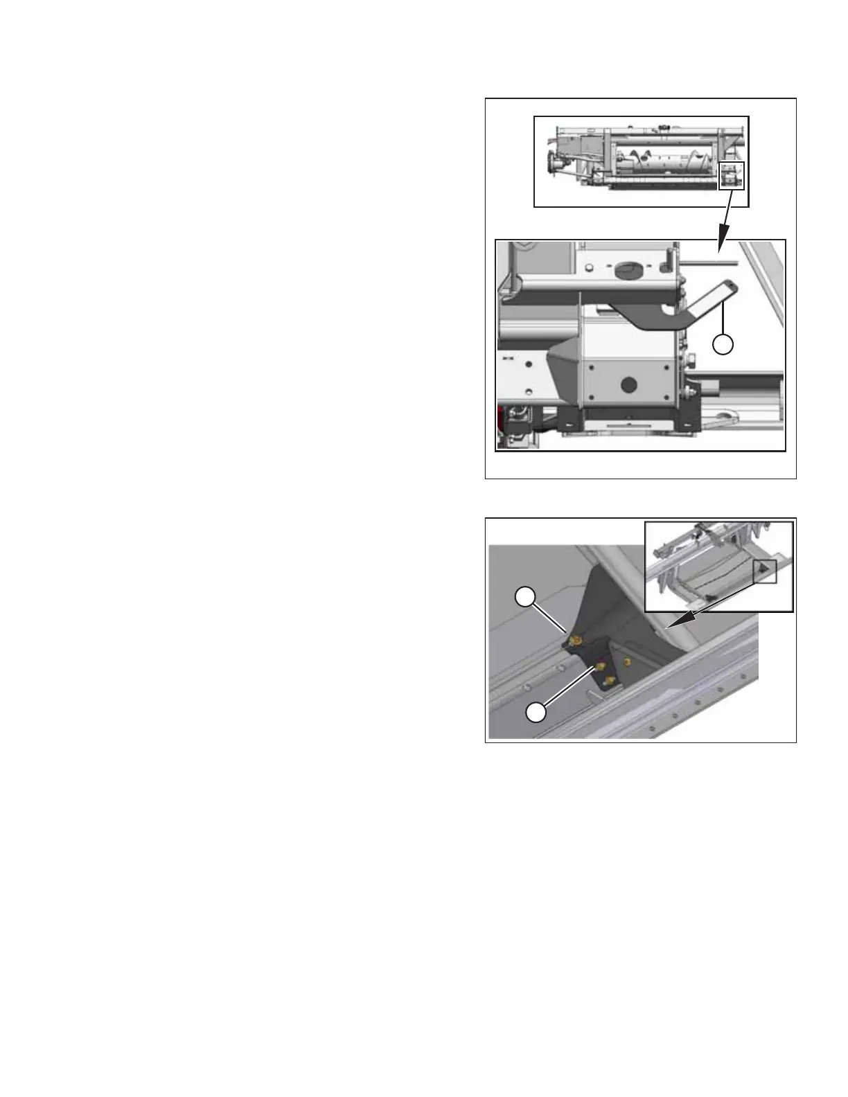
Figure 5.97: Float Locked
6. Engage both float locks by lifting each lock lever (A)
upwards until it latches into the lock position.
NOTE:
Stabilizer/Slow Speed Transport wheels can be used to
support the header.
Figure 5.98: Fillers
7. Remove two bolts (A) attaching filler (B) to the transition
pan at the front corners.
8. Fold back filler (B) to access the latch.
HEADER ATTACHMENT/DETACHMENT