214323 333 Revision B
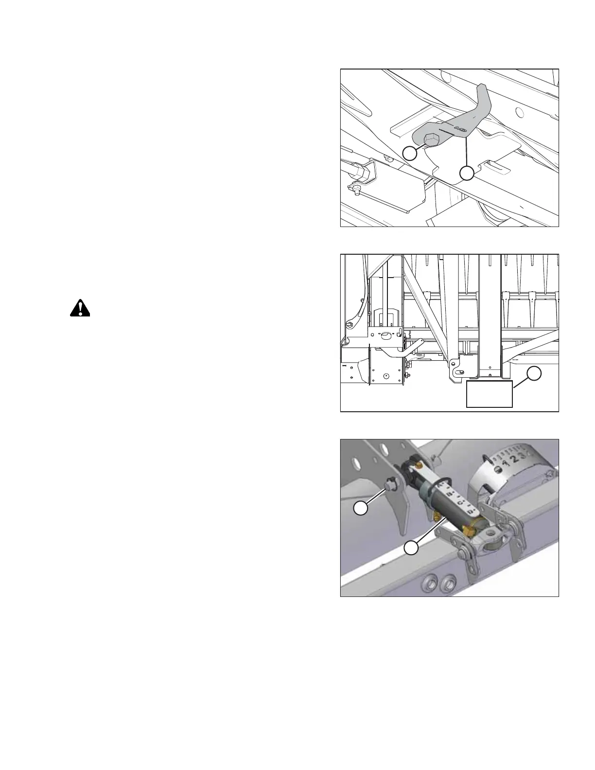
Figure 5.101: Adapter Underside
21. Rotate hook (B) 90° for storage, and retighten bolt (A)
and nut.
Figure 5.102: Header Leg on Block
22. Place 150 mm (6 in.) block (A) under the header leg.
23. Disengage combine lift cylinder locks.
DANGER
Ensure that all bystanders have cleared the area.
24. Start the engine.
25. Lower the header until the header leg rests on the block or
until the stabilizer wheels are on the ground.
Figure 5.103: Hydraulic Center-Link
26. Disconnect the hydraulic center-link as follows:
a. Remove lynch pin and clevis pin (A), and lift
center-link (B) clear of the bracket.
b. Replace clevis pin (A) and secure with lynch pin.
NOTE:
It may be necessary to raise or lower the feeder house
to adjust the length of the center-link and relieve the
excess load on the center-link.
HEADER ATTACHMENT/DETACHMENT