214323 336 Revision B
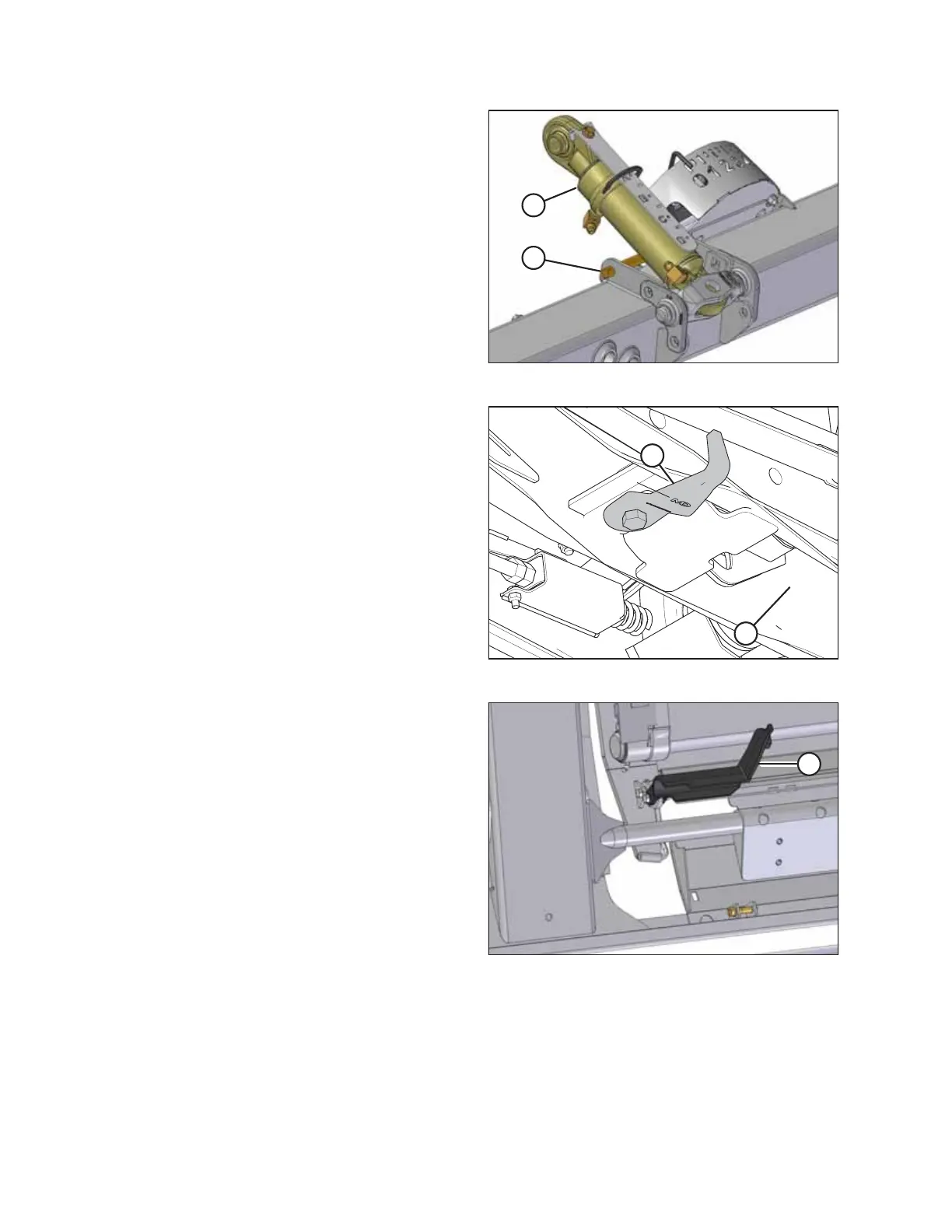
Figure 5.109: Center-Link
1. Prop up hydraulic center-link (A) with a pin (or equivalent
tool) at location (B) as shown in the illustration.
Figure 5.110: Header Underside
2. Ensure hooks (A) are in the storage position as shown. Do
NOT interfere with the installation of the adapter arms into
channel (B).
Figure 5.111: Latch
3. Rotate latches (A) towards the rear of the adapter.
HEADER ATTACHMENT/DETACHMENT