214323 411 Revision B
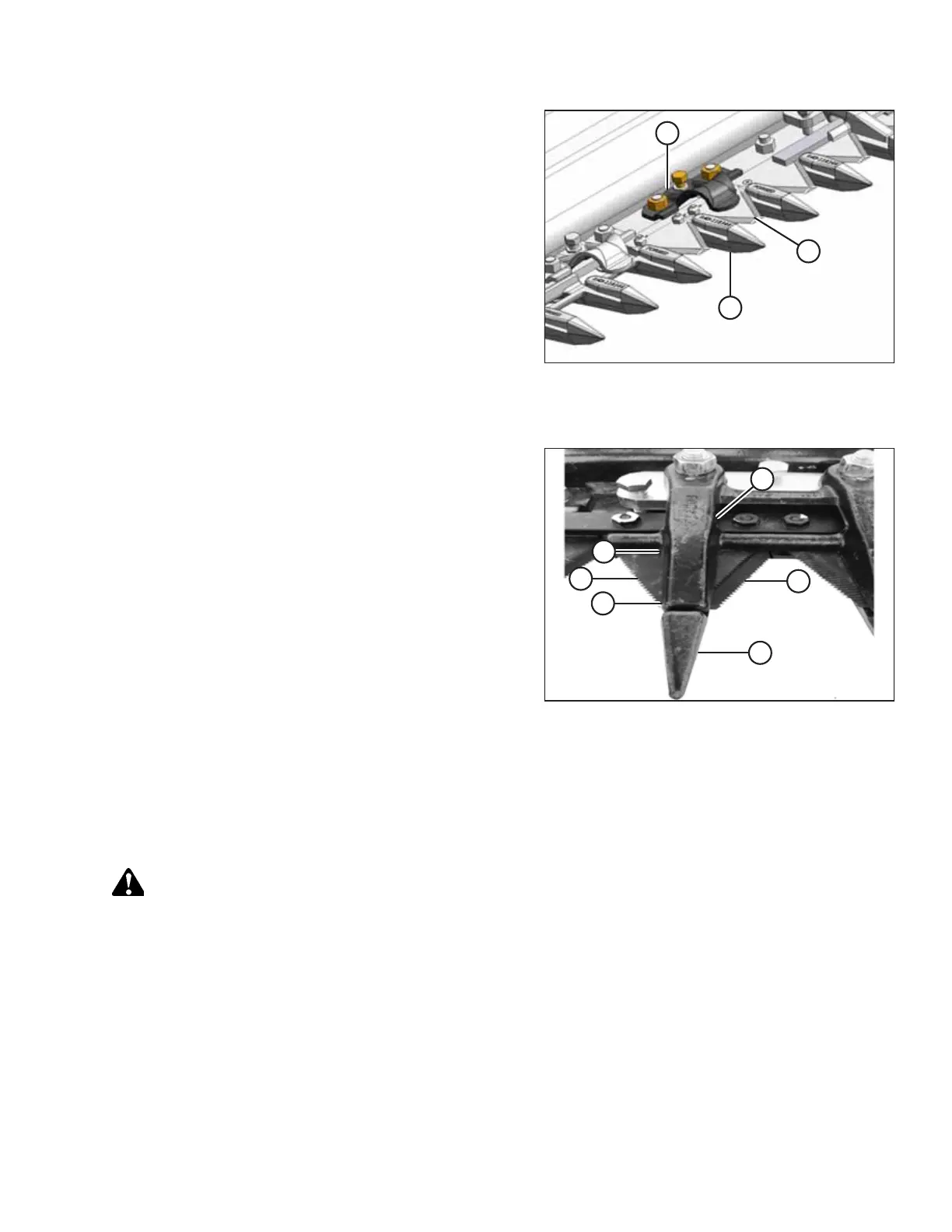
Figure 6.120: Normal Guard Hold-Down
3. Manually stroke the knife to align section (A) under
hold-down (B).
4. At standard guard locations, push knife section (A) down
against guard (C) and measure the clearance between hold-
down (B) and knife section (A) with a feeler gauge. The
clearance should be 0.1–0.6 mm (0.004–0.024 in.).
5. If necessary, refer to Adjusting Pointed Guard Hold-Downs,
page 411.
Double knife
Figure 6.121: Double-Knife Center Guard Hold-Down
6. Manually stroke the knife to align sections (A) and (C) under
center hold-down (B).
7. Measure between knife sections (A) and (C) with a feeler
gauge. The clearances should be as follows:
• At tip of hold-down: 0.1–0.4 mm (0.004–0.016 in.)
• At rear of hold-down: 0.1–1.0 mm (0.004–0.040 in.)
8. If necessary, refer to Adjusting Hold-Down Clips at Double-
Knife Center Pointed Guard, page 412.
Adjusting Pointed Guard Hold-Downs
This procedure is applicable to formed sheet metal hold-downs. Do NOT use this procedure for the hold-down at the
center guard position where knives overlap on double-knife headers.
For the center guard, refer to Adjusting Hold-Down Clips at Double-Knife Center Pointed Guard, page 412.
DANGER
To prevent bodily injury or death from the unexpected startup of the machine, always stop the engine and remove the
key before adjusting the machine.
1. Shut down the engine, and remove the key from the ignition.
MAINTENANCE AND SERVICING