214323 484 Revision B
Figure 6.276: Bushing
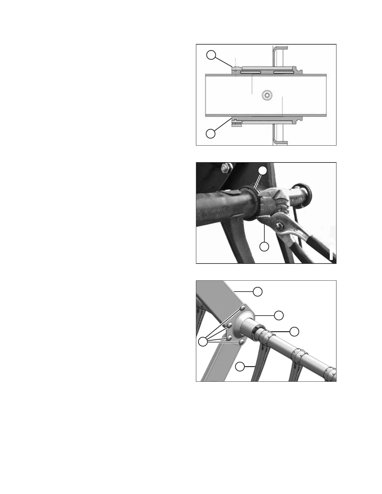
23. Install bushing clamp (A) onto the tine tube adjacent to the
flangeless end of bushing (B).
24. Position clamp (A) on bushing (B) so the edges of the clamp
and bushing are flush when the clamp is fit into the groove
on the bushing and the lock tabs are engaged.
Figure 6.277: Clamp on Bushing
25. Tighten clamp (A) using modified channel lock pliers (B)
until finger pressure will NOT move the clamp.
IMPORTANT:
Overtightening the clamp might break the clamp.
Figure 6.278: Tine Tube Support
26. Reattach channels (C) to support (A) with screws (B) and
nuts. Torque the screws to 43 Nm (32 lbf∙ft).
27. Reinstall any fingers (D) that were previously removed
using screws (E). For instructions, refer to Installing Plastic
Fingers, page 472.
MAINTENANCE AND SERVICING