309978-D Rev 01 xv
Figures
Figure 1-1. BayStack 450 Switch Versions .................................................................2-2
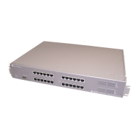
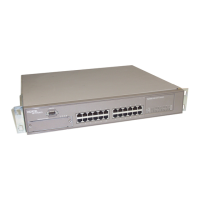
Figure 1-2. BayStack 450 Switch Front Panels ..........................................................2-3
Figure 1-3. BayStack 450-24T/12T LED Display Panel ..............................................2-6
Figure 1-4. BayStack 450-12F LED Display Panel .....................................................2-7
Figure 1-5. BayStack 450 Switch Back Panel ..........................................................2-10
Figure 1-6. BayStack 450 Switch Security Feature Example ...................................2-18
Figure 1-7. EAPOL-Based Security (1 of 2) .............................................................2-22
Figure 1-8. EAPOL-Based Security (2 of 2) .............................................................2-22
Figure 1-9. Authentication Process Flowchart (1 of 2) .............................................2-26
Figure 1-10. Authentication Process Flowchart (2 of 2) .............................................2-27
Figure 1-11. BayStack 450 Switch Used as a Desktop Switch ..................................2-33
Figure 1-12. BayStack 450 Switch Used as a Segment Switch .................................2-34
Figure 1-13. Configuring Power Workgroups and a Shared Media Hub ....................2-35
Figure 1-14. Configuring an ATM Application .............................................................2-36
Figure 1-15. Fail-Safe Stack Example ........................................................................2-38
Figure 1-16. Compatible Software Versions ...............................................................2-39
Figure 1-17. BayStack 400-ST1 Front-Panel Components ........................................2-41
Figure 1-18. Connecting Cascade Cables .................................................................2-42
Figure 1-19. Stack Up Configuration Example ...........................................................2-46
Figure 1-20. Stack Down Configuration Example ......................................................2-47
Figure 1-21. Redundant Cascade Stacking Feature ..................................................2-49
Figure 1-22. Port-Based VLAN Example ....................................................................2-51
Figure 1-23. Default VLAN Settings ...........................................................................2-53
Figure 1-24. Port-Based VLAN Assignment ...............................................................2-54
Figure 1-25. 802.1Q Tagging (After Port-Based VLAN Assignment) .........................2-55
Figure 1-26. Protocol-Based VLAN Assignment ........................................................2-55
Figure 1-27. 802.1Q Tagging (After Protocol-Based VLAN Assignment) ...................2-56
Figure 1-28. 802.1Q Tag Assignment .........................................................................2-57
Figure 1-29. 802.1Q Tagging (After 802.1Q Tag Assignment) ...................................2-57