13
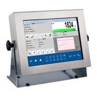
5.2.4. Connector with RS232 and I/O
Pin2 – RxD
Pin3 – TxD
Pin4 – 5VDC
Pin5 – GND
RS232 connector
(COM1) DB9/M
(male)
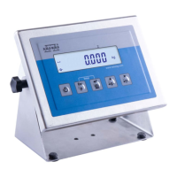
Pin1 – GND_IN
Pin2 - OUT1
Pin3 - OUT2
Pin4 - COMM
Pin5 - 6÷9VDC
Pin6 - IN4
Pin7 - IN3
Pin8 - TxD2
Pin9 - 5VDC
Pin10 - GNDRS
Pin11 - IN2
Pin12 - IN1
Pin13 - RxD2
Pin14 - OUT4
Pin15 - OUT3
IN/OUT connector,
RS232 (COM2)
DSUB15/F
(female)
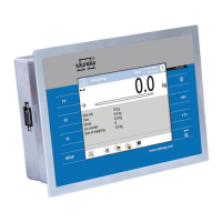
6. GETTING STARTED
• After the indicator is connected to power the ON/LOAD
diode starts to light.
• Press
to start the operating system loading procedure.
Windows CE together with RADWAG software loading is signalled
by blinking the red diode ON/LOAD.
• When the loading procedure is completed the main software
window appears.
 Loading...