RL78/G10 CHAPTER 6 TIMER ARRAY UNIT
R01UH0384EJ0311 Rev. 3.11 202
Dec 22, 2016
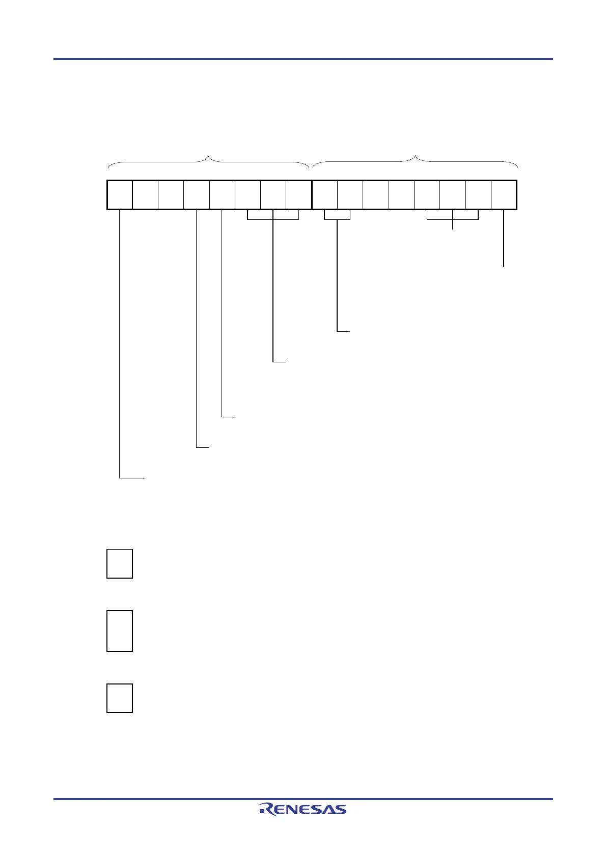
Figure 6-72. Example of Set Contents of Registers for Two-channel Input with One-shot Pulse Output Function
(Slave Channel) (1/2)
(a) Timer mode register 0p (TMR0pH, TMR0pL)
TMR0pH TMR0pL
7 6 5 4 3 2 1 0 7 6 5 4 3 2 1 0
TMR0p
CKS0p1
1/0
0
0
CCS0p
0
S
0
STS0p2
1
STS0p1
1
STS0p0
0
CIS0p1
0
CIS0p0
0
0
0
MD0p3
0
MD0p2
1
MD0p1
0
MD0p0
0
Operation mode of channel p
010B: Capture mode
Setting of operation when counting
is started
0: Does not generate INTTM0n
when counting is started.
Selection of TI0p pin input edge
00B: Detects falling edge.
Trigger selection
110B: Selects INTTM0n of master channel as the start trigger and
selects TI0p pin input valid edge of slave channel as the end trigger
(capture trigger).
Setting of SPLIT0p bit (Channel 3)
0: 16-bit timer
Count clock selection
0: Selects operation clock (f
MCK).
Operating clock (f
MCK) selection
0: Selects CK00 as operating clock of channel p.
1: Selects CK01 as operating clock of channel p.
* Make the same setting as master channel.
(b) Timer output register 0 (TO0)
Bit p
TO0
TO0p
1/0
0: Outputs 0 from TO0p.
1: Outputs 1 from TO0p.
(c) Timer output enable register 0 (TOE0)
Bit p
TOE0
TOE0p
1/0
0: Stops the TO0p output operation by counting operation (the level set in the TO0p bit is output from the
TO0p pin).
1: Enables the TO0p output operation by counting operation (output from the TO0p pin is toggled).
(d) Timer output level register 0 (TOL0)
Bit p
TOL0
TOL0p
1/0
0: Positive logic output (active-high)
1: Negative logic output (active-low)
Remark n: Master channel number (n = 0, 2)
p: Slave channel number (p = 3)

 Loading...


