RL78/G10 CHAPTER 6 TIMER ARRAY UNIT
R01UH0384EJ0311 Rev. 3.11 210
Dec 22, 2016
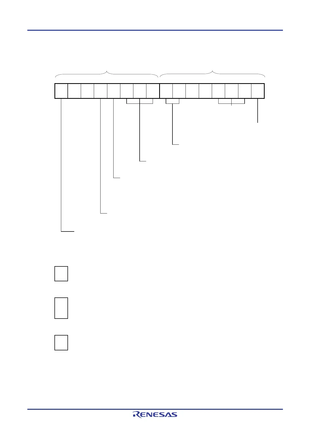
Figure 6-77. Example of Set Contents of Registers for PWM Output Function (Slave Channel) (1/2)
(a) Timer mode register 0p (TMR0pH, TMR0pL)
TMR0pH TMR0pL
15 14 13 12 11 10 9 8 7 6 5 4 3 2 1 0
TMR0p
CKS0p1
1/0
0
0
CCS0p
0
M/S
Note
1/0
STS0p2
1
STS0p1
0
STS0p0
0
CIS0p1
0
CIS0p0
0
0
0
MD0p3
1
MD0p2
0
MD0p1
0
MD0p0
1
Operation mode of channel p
100B: One-count mode
Start trigger during operation
1: Trigger input is valid.
Selection of TI0p pin input edge
00B: Sets 00B because these are not used.
Start trigger selection
100B: Selects INTTM0n of master channel.
Setting of MASTER0p bit (Channel 2)
0: Slave channel
Setting of SPLIT0p bit (Channel 1, 3)
0: 16-bit timer
1: 8-bit timer
Count clock selection
0: Selects operation clock (f
MCK).
Operation clock (f
MCK) selection
0: Selects CK00 as operation clock of channel p.
1: Selects CK01 as operation clock of channel p.
* Make the same setting as master channel.
(b) Timer output register 0 (TO0)
Bit p
TO0
TO0p
1/0
0: Outputs 0 from TO0p.
1: Outputs 1 from TO0p.
(c) Timer output enable register 0 (TOE0)
Bit p
TOE0
TOE0p
1/0
0: Stops the TO0p output operation by counting operation (the level set in the TO0p bit is output from the
TO0p pin).
1: Enables the TO0p output operation by counting operation (output from the TO0p pin is toggled).
(d) Timer output level register 0 (TOL0)
Bit p
TOL0
TOL0p
1/0
0: Positive logic output (active-high)
1: Negative logic output (active-low)
Note TMR02: MASTER0p bit
TMR01, TMR03: SPLIT0p bit
Remark n: Master channel number (n = 0, 2)
p: Slave channel number (n < p ≤ 3)

 Loading...


