RL78/G10 CHAPTER 6 TIMER ARRAY UNIT
R01UH0384EJ0311 Rev. 3.11 209
Dec 22, 2016
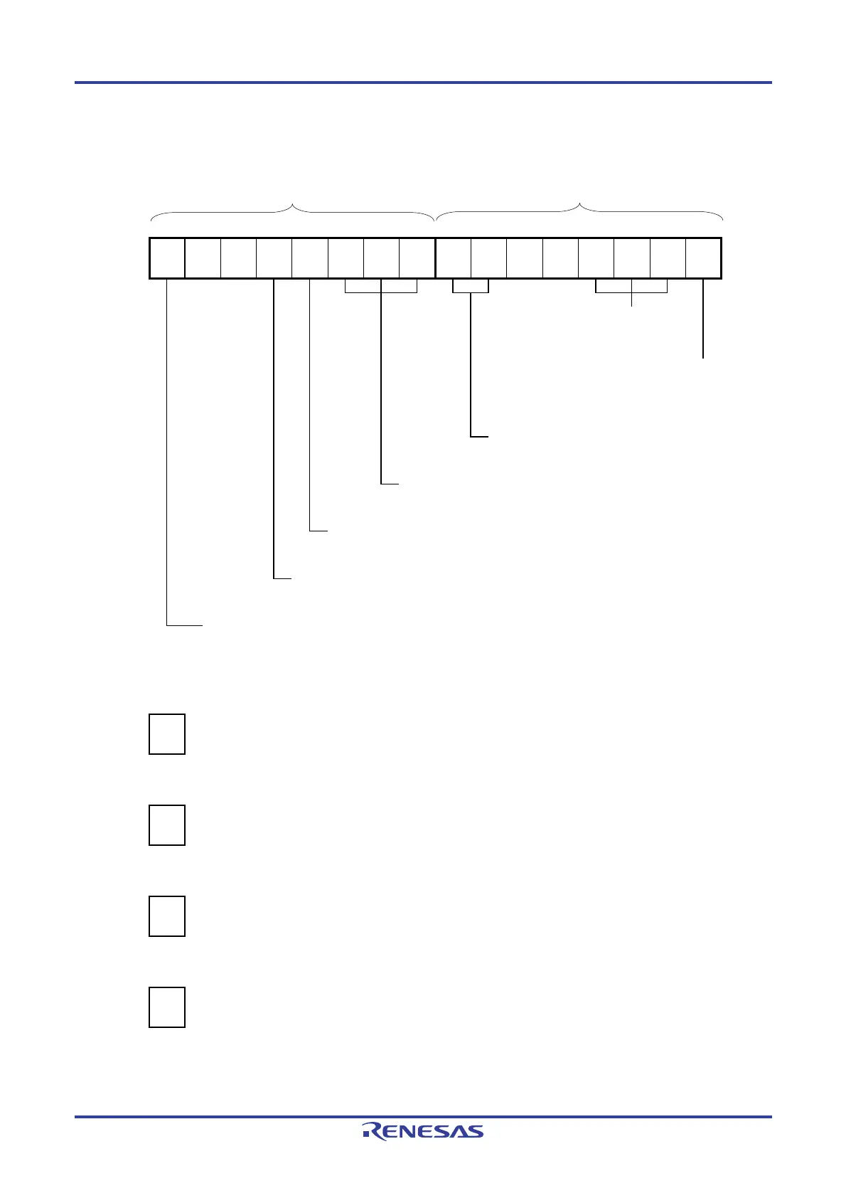
Figure 6-76. Example of Set Contents of Registers for PWM Output Function (Master Channel)
(a) Timer mode register 0n (TMR0nH, TMR0nL)
TMR0nH TMR0nL
15 14 13 12 11 10 9 8 7 6 5 4 3 2 1 0
TMR0n
CKS0n1
1/0
0
0
CCS0n
0
M
Note
1
STS0n2
0
STS0n1
0
STS0n0
0
CIS0n1
0
CIS0n0
0
0
0
MD0n3
0
MD0n2
0
MD0n1
0
MD0n0
1
Operation mode of channel n
000B: Interval timer
Setting of operation when counting is started
1: Generates INTTM0n when counting is
started.
Selection of TI0n pin input edge
00B: Sets 00B because these are not used.
Start trigger selection
000B: Selects only software start.
Setting of MASTER0n bit (Channel 2)
1: Master channel.
Count clock selection
0: Selects operation clock (f
MCK).
Operation clock (f
MCK) selection
0: Selects CK00 as operation clock of channel n.
1: Selects CK01 as operation clock of channel n.
(b) Timer output register 0 (TO0)
Bit n
TO0
TO0n
0
0: Outputs 0 from TO0n.
(c) Timer output enable register 0 (TOE0)
Bit n
TOE0
TOE0n
0
0: Stops the TO0n output operation by counting operation.
(d) Timer output level register 0 (TOL0)
Bit n
TOL0
TOL0n
0
0: Setting is invalid because master channel output mode is set (TOM0n = 0).
(e) Timer output mode register 0 (TOM0)
Bit n
TOM0
TOM0n
0
0: Sets master channel output mode.
Note TMR02: MASTER02 bit
TMR00: 0 fixed
Remark n: Master channel number (n = 0, 2)

 Loading...


