RL78/G10 CHAPTER 6 TIMER ARRAY UNIT
R01UH0384EJ0311 Rev. 3.11 213
Dec 22, 2016
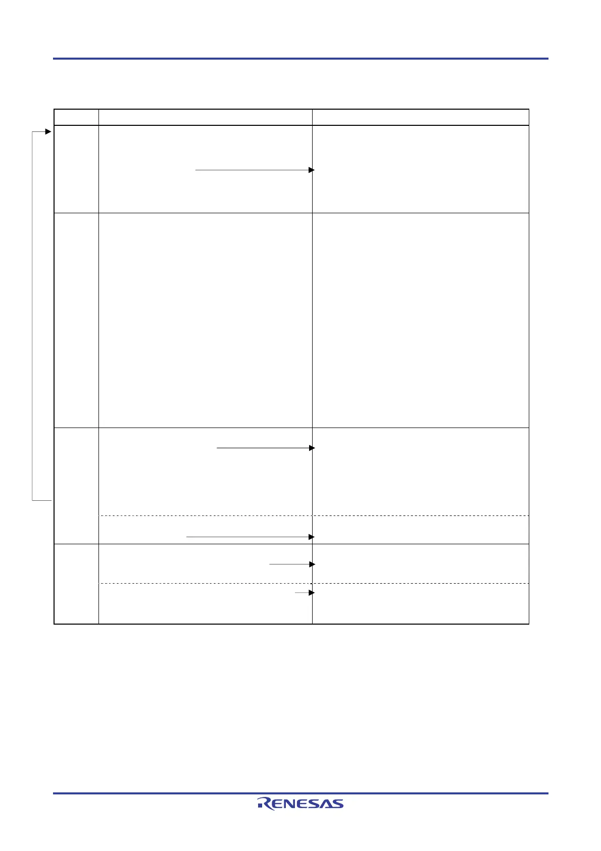
Figure 6-78. Procedure for Using PWM Output Function (2/2)
Software Operation Hardware Status
Operation
start
Sets the TOE0p bit of the slave register to 1 and enables
operation of TO0n (only when operation is resumed).
Sets the target bits (master and slave) of the TS0 register
to 1 at the same time.
The target bits of the TS0 register automatically return
to 0 because they are trigger bits.
The target bit of the TE0 register is set to 1, and the timer
counter register 0n (TCR0n) of the master channel is
loaded with the TDR0n register value and starts
counting down.
During
operation
Changes master channel setting.
The set values of the TDR0n register can be changed
after INTTM0n of the master channel is generated.
The TCR0n register can always be read (for the
access procedure to the TCR0nH and TCR0nL
registers, see 6.2.1 Timer counter register 0n
(TCR0n)).
The set values in the target bits of the TMR0n, TO0,
TOE0, TOM0, and TOL0 registers cannot be changed.
Changes slave channel setting.
The set values of the TDR0p register can be changed
after INTTM0n of the master channel is generated.
The TCR0p register can always be read.
The set values in the target bits of the TO0, TOE0, and
TOL0 registers can be changed.
The set values in the target bits of the TMR0p and
TOM0 registers cannot be changed.
The timer counter register 0n (TCR0n) of the master
channel performs count down operation. When the count
value reaches TCR0n = 0000H, INTTM0n output is
generated. At the same time, the value of the TDR0n
register is loaded to the TCR0n register, and the counter
starts counting down again.
At the slave channel, the value of the TDR0p register is
loaded to the TCR0p register, triggered by INTTM0n of
the master channel, and the counter starts counting down.
The output level of TO0p becomes active one count clock
(f
TCLK) after generation of the INTTM0n output from the
master channel. It becomes inactive when TCR0p =
0000H, and the counting operation is stopped with TCR0p
= FFFFH.
After that, the above operation is repeated.
Operation
stop
Sets the target bits of the TT0 registers (master and
slave) to 1 at the same time.
The target bits of the TT0 registers automatically return
to 0 because they are trigger bits.
The target bits of the TE0 register are cleared to 0, and
count operation stops.
The TCR0n and TCR0p registers hold count value and
stop.
The TO0p output is not initialized but holds current
status.
Clears the TOE0p bit of slave channel to 0 and sets a
value to the TO0p bit.
The level set in the TO0p bit is output from the TO0p pin.
TAU
stop
To hold the TO0p pin output level
Clears the TO0p bit to 0 after the value to
be held (output latch) is set to the port register.
The TO0p pin output level is held by port function.
Clears the TAU0EN bit of the PER0 register to 0.
Power-off status
(Clock supply is stopped and SFR of the TAU is
initialized.)
Remark n: Master channel number (n = 0, 2)
p: Slave channel number (n < p ≤ 3)
Operation is resumed.

 Loading...


