RL78/G10 CHAPTER 12 SERIAL ARRAY UNIT
R01UH0384EJ0311 Rev. 3.11 324
Dec 22, 2016
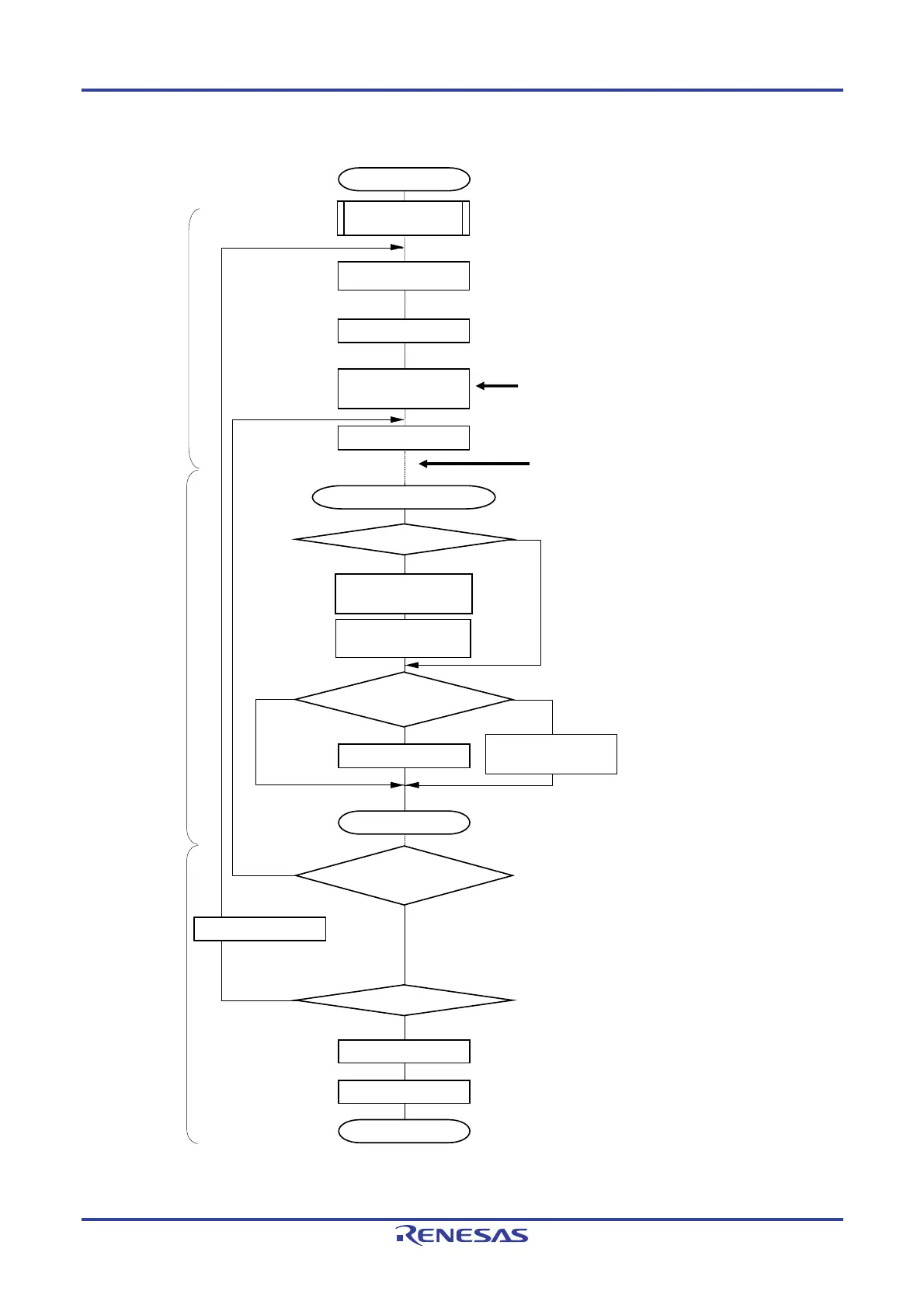
Figure 12-37. Flowchart of Master Reception (in Continuous Reception Mode)
Starting CSI communication
Reading receive data to SIOp
(=SDR0nL)
Write 1 to ST0n bit
=
No
End of communication
Clear MD0n0 bit to 0
Communication continued
Yes
Writing dummy data to
SIOp (=SDR0nL)
<2>
<3>
<5>
<6>
<7>
<4>
<8>
No
Yes
BFF0n = 1?
For the initial setting, refer to Figure 12-31.
(Select
buffer empty interrupt)
SAU default setting
Setting receive data
Setting storage area of the receive data, number of communication data
(Storage area, Reception data pointer, Number of communication data and
Communication end flag are optionally set on the internal RAM by the software)
Wait for receive completes
Buffer empty/transfer end interrupt
≥ 2
Number of communication
data?
Writing to SIOp makes SCKp
signals out (communication starts)
When interrupt is generated, it moves to
interrupt processing routine
Subtract -1 from number of
transmit data
<1>
Read receive data, if any, then write them to storage
area, and update receive data pointer (also subtract -1
from number of transmit data)
Writing dummy data to
SIOp (=SDR0nL)
= 0
<2>
RETI
No
Number of communication
data = 0?
Yes
When number of communication data
becomes 0, receive completes
Enables interrupt
Clear interrupt request flag (XXIF), reset interrupt mask (XXMK) and set
interrupt enable (EI)
Write 1 to MD0n0 bit
Disable interrupt (MASK)
Main routine
Main routine
Interrupt processing routine
Remark <1> to <8> in the figure correspond to <1> to <8> in Figure 12-36 Timing Chart of Master Reception
(in Continuous Reception Mode).

 Loading...


