RL78/G10 CHAPTER 23 INSTRUCTION SET
R01UH0384EJ0311 Rev. 3.11 584
Dec 22, 2016
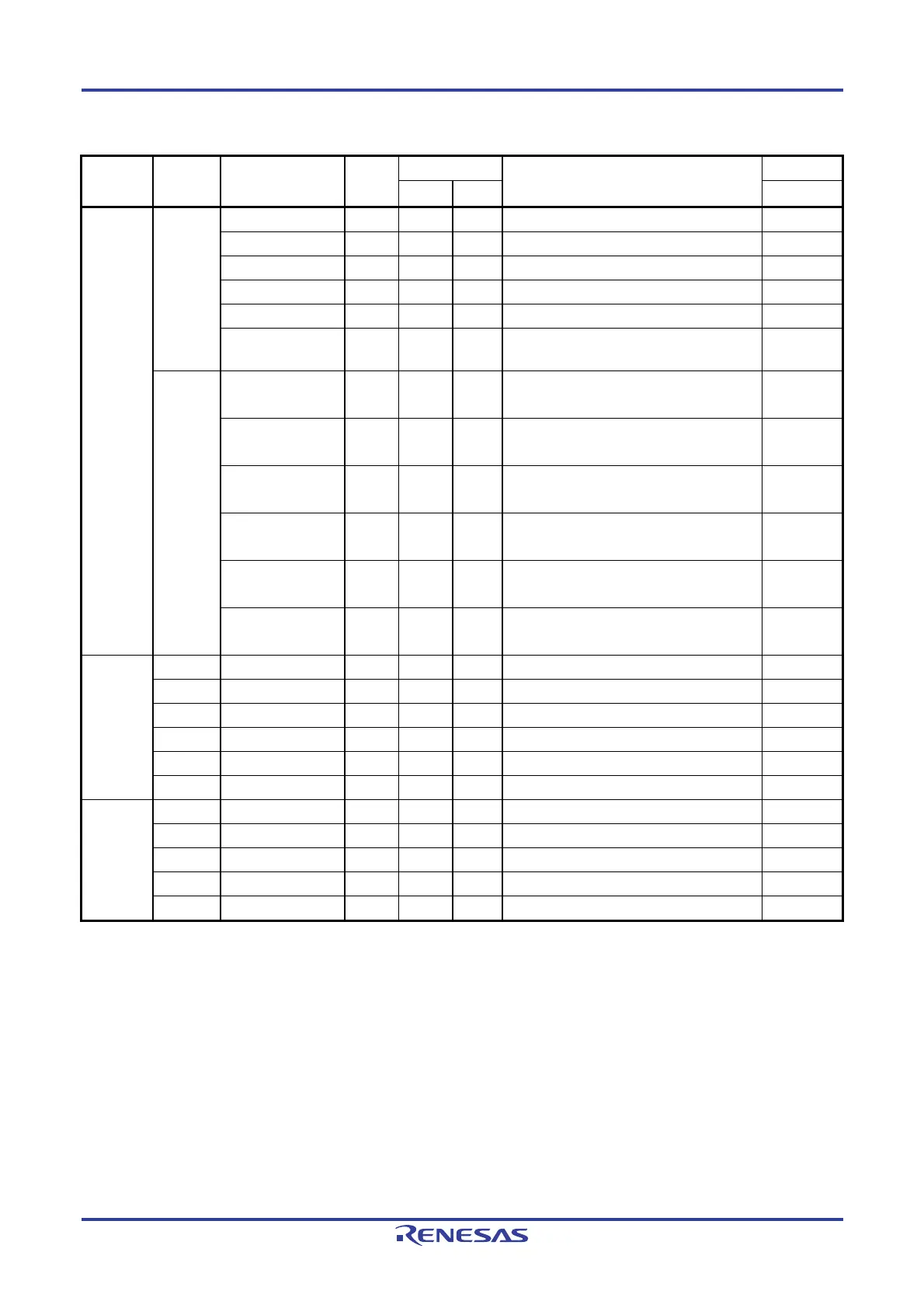
Table 23-5. Operation List (17/17)
Notes 1. Number of CPU clocks (fCLK) when the internal RAM area, SFR area, or extended SFR area is accessed, or
when no data is accessed.
2. Number of CPU clocks (f
CLK) when the code flash memory is accessed.
3. This indicates the number of clocks “when condition is not met/when condition is met”.
Remark These numbers of clock cycles apply when the program is in the internal ROM (flash memory) area. When the
instruction is fetched from the internal RAM area, the number is, at most, the quadruple of the number given
here plus 6 further clock cycles.
Instruction
Group
Mnemonic Operands Bytes Clocks Clocks Flag
Note 1 Note 2 ZACCY
Conditional
branch
BF saddr.bit, $addr20 4 3/5
Note3
−
PC ← PC + 4 + jdisp8 if (saddr).bit = 0
sfr.bit, $addr20 4 3/5
Note3
−
PC ← PC + 4 + jdisp8 if sfr.bit = 0
A.bit, $addr20 3 3/5
Note3
−
PC ← PC + 3 + jdisp8 if A.bit = 0
PSW.bit, $addr20 4 3/5
Note3
−
PC ← PC + 4 + jdisp8 if PSW.bit = 0
[HL].bit, $addr20 3 3/5
Note3
6/7 PC ← PC + 3 + jdisp8 if (HL).bit = 0
ES:[HL].bit,
$addr20
4 4/6
Note3
7/8 PC ← PC + 4 + jdisp8 if (ES, HL).bit = 0
BTCLR saddr.bit, $addr20 4 3/5
Note3
−
PC ← PC + 4 + jdisp8 if (saddr).bit = 1
then reset (saddr).bit
sfr.bit, $addr20 4 3/5
Note3
−
PC ← PC + 4 + jdisp8 if sfr.bit = 1
then reset sfr.bit
A.bit, $addr20 3 3/5
Note3
−
PC ← PC + 3 + jdisp8 if A.bit = 1
then reset A.bit
PSW.bit, $addr20 4 3/5
Note3
−
PC ← PC + 4 + jdisp8 if PSW.bit = 1
then reset PSW.bit
×××
[HL].bit, $addr20 3 3/5
Note3
−
PC ← PC + 3 + jdisp8 if (HL).bit = 1
then reset (HL).bit
ES:[HL].bit,
$addr20
4 4/6
Note3
−
PC ← PC + 4 + jdisp8 if (ES, HL).bit = 1
then reset (ES, HL).bit
Conditional
skip
SKC
−
2 1
−
Next instruction skip if CY = 1
SKNC
−
2 1
−
Next instruction skip if CY = 0
SKZ
−
2 1
−
Next instruction skip if Z = 1
SKNZ
−
2 1
−
Next instruction skip if Z = 0
SKH
−
2 1
−
Next instruction skip if (Z∨CY)=0
SKNH
−
2 1
−
Next instruction skip if (Z∨CY)=1
CPU
control
NOP
−
1 1
−
No Operation
EI
−
3 4
−
IE ← 1 (Enable Interrupt)
DI
−
3 4
−
IE ← 0 (Disable Interrupt)
HALT
−
2 3
−
Set HALT Mode
STOP
−
2 3
−
Set STOP Mode

 Loading...