6.16
SEL-2414 Transformer Monitor Instruction Manual Date Code 20130214
Settings
Global Settings (SET G Command)
Figure 6.8 shows a timing diagram when IN101R changes from the deasserted
state to the asserted state. At the first assertion of IN101R, the following takes
place:
➤ Device Word bit IN101E asserts
➤ Debounce Timer 2 starts
➤ All edge changes are ignored
If you want to record the time of first assertion of IN101, be sure to enter Device
Word bit IN101E in the SER (see Report Settings (SET R Command) on
page SET.33). During the time when Debounce Timer 2 runs, the device ignores
all edge changes. At the end of this timing period, the device evaluates the status
of IN101R (either logical 0, or logical 1), and sets Device Word bit IN101E to
this value. In Figure 6.8, IN101R has a status of logical 1 and Device Word bit
IN101E remains at logical 1.
Device Word bit IN101 asserts only if IN101R stays asserted for the complete
duration of Debounce Timer 1. If IN101R deasserts at any point while Debounce
Timer 1 is running, Debounce Timer 1 resets, and starts timing from the begin-
ning at the next rising edge.
When changing from the asserted state to the deasserted state, the inverse opera-
tion applies, as shown in Figure 6.9.
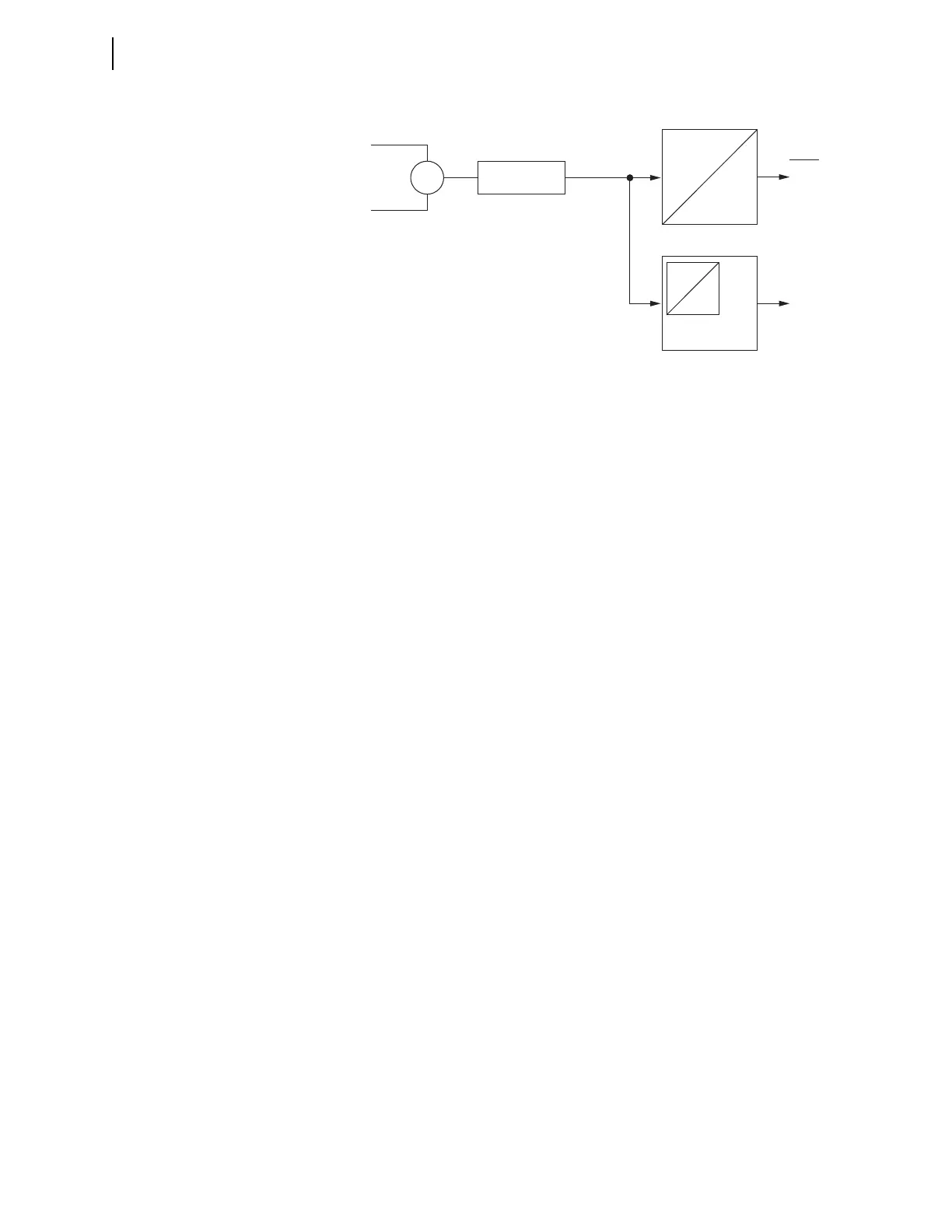
Figure 6.7 DC Mode Processing
pu
pu
do
do
Edge Detect
Logic
IN101
IN101E
Device
Word
Bits
Input IN101
IN101R
Analog/Digital
Converter
Debounce Timer 1
Debounce Timer 2