6.17
Date Code 20130214 Instruction Manual SEL-2414 Transformer Monitor
Settings
Global Settings (SET G Command)
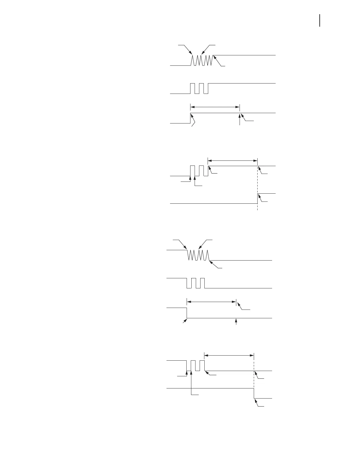
Figure 6.8 Timing Diagram When IN101R Changes From the Deasserted State
to the Asserted State
Figure 6.9 Timing Diagram When Input IN101 Changes From the Asserted State
to the Deasserted State
Contact Connected
to Input IN101
Contact Bounce
Contact Solidly Asserted
First Assertion
IN101R
IN101E
1. Asserts IN101E
2. Starts Debounce Timer 2
3. Ignores Edges
Debounce Time (IN101D Setting)
1. Sets IN101E = IN101R
2. Considers Edges
IN101 Asserts
Debounce
Timer 1
IN101
Debounce
Timer 1 Starts
Debounce
Timer 1 Starts
Debounce
Timer 1 Stops
Debounce Time (IN101D Setting)
Debounce Timer 1 Expires
Debounce Timer 2 Expires
Contact Connected
to Input IN101
Contact Bounce
Contact Solidly Deasserted
First Deassertion
IN101R
IN101E
1. Deasserts IN101E
2. Starts Debounce (do) Timer 2
3. Ignores Edges
Debounce Time (IN101D Setting)
1. Sets IN101E = IN101R
2. Considers Edges
IN101 Deasserts
Debounce
Timer 1
IN101
Debounce
Timer 1 (do) Starts
Debounce
Timer 1 (do) Starts
Debounce
Timer 1 (do) Stops
Debounce Time (IN101D Setting)
Debounce Timer 1 (do) Expires
Debounce Timer 2 (do) Expires