5.12
SEL-2414 Transformer Monitor Instruction Manual Date Code 20130214
Metering and Monitoring
Monitoring
ETHERM = W
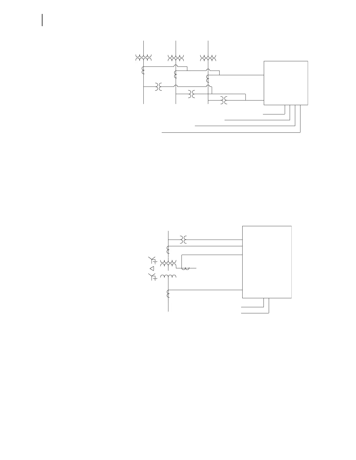
Set ETHERM = W to monitor a three-winding transformer where power is drawn
from all three windings. If the tertiary is buried, use the ETHERM = 1 mode. See
Figure 5.12 for a sample one-line diagram with the voltage, current, and temper-
ature measurements. The thermal element does not use the voltage measure-
ments; these are optional and if included, will provide more metering data. The
settings TMWNOM, TMWNOM2, and TMWNOM3 define the nominal voltage
of the windings to which the current measurements are connected. There must be
one current measurement from each of the three windings.
The measurement for the primary winding (Winding/Transformer 1) must be
wired to the Phase A input, or listed as the first Analog Quantity under TMWAQ.
The measurement for the secondary winding (Winding/Transformer 2) must be
wired to the Phase B input, or listed as the second Analog Quantity under
TMWAQ. The measurement for the tertiary winding (Winding/Transformer 3)
must be wired to the Phase C input, or listed as the third Analog Quantity under
TMWAQ.
In most cases, the three CTs will have different CT ratios. To accommodate this,
either use the 3AVI/3ACI card in Slot E to use the different CT ratio settings for
each CT input, or use math variables to provide the appropriate multiplication
factor for each measured phase current and set TMWAQ to use the respective
math variables.
Figure 5.11 ETHERM = 3 Connection Diagram
Ambient RTD/TC
Top Oil RTD/TC #3
Top Oil RTD/TC #2
To
Oil RTD/TC #1
1
1
1
1
1
IA, IB, IC
VA, VB, VC
SEL-2414
1
Figure 5.12 ETHERM = W Connection Diagram
Ambient RTD/TC
Top Oil RTD/TC
3
1
1
1
IA
IB
IC
VA, VB, VC
SEL-2414