5.24
SEL-2414 Transformer Monitor Instruction Manual Date Code 20130214
Metering and Monitoring
Monitoring
Cooling Stage Activation (TxCSy)
Range: SELOGIC control equation
The thermal element uses the output of SEL
OGIC control equations to determine
which cooling stage is active, so that thermal element calculations use the correct
transformer constants. The settings ETHERM and NUMCS determine the
number of SEL
OGIC control equations the relay will prompt the user for.
The TxCSy SEL
OGIC control equations can be set to any of the Device Word bits
except Row 0 and Row 1 of Table 4.9. However, it is critical that they be
configured to accurately indicate which cooling system is active. In the simplest
implementation, this will consist of one or two external contacts from the
monitored power transformer connected to optoisolated inputs on the SEL-2414
with the CsxyS SEL
OGIC control equations set to the corresponding digital input.
See Cooling Stage Determination on page 5.15 for more information.
Default Ambient Temperature (D_AMB)
Range: –50° to 100°C, in 1°C steps
Select a reasonable value for D_AMB, in degrees Celcius to be used as the
ambient temperature in case the measured ambient measurement fails. The
ambient measurement will be used if MAMB_OK deasserts. See setting
description for AMB_F for more information.
Transformer De-Energized (TRDE)
Range: SELOGIC control equation
Transformer heating consists of heating resulting from transformer no load losses
and heating resulting from load losses. IEEE standard C57.91-1995 assumes the
transformer is energized and calculates an increase in oil and winding hot-spot
temperatures resulting from transformer no-load losses. Device Word bit TRDE
provides the thermal element a way to distinguish between the de-energized and
energized stages. For example, wire a 52b (normally closed) circuit breaker
auxiliary contact to input IN101 and enter the SEL
OGIC control equation TRDE =
IN101. When IN101 asserts (circuit breaker main contacts open and the 52b
auxiliary contacts closed), the thermal element considers the transformer de-
energized and the ambient, top-oil, and hot-spot temperatures will equalize to all
have the same temperature, given enough time.
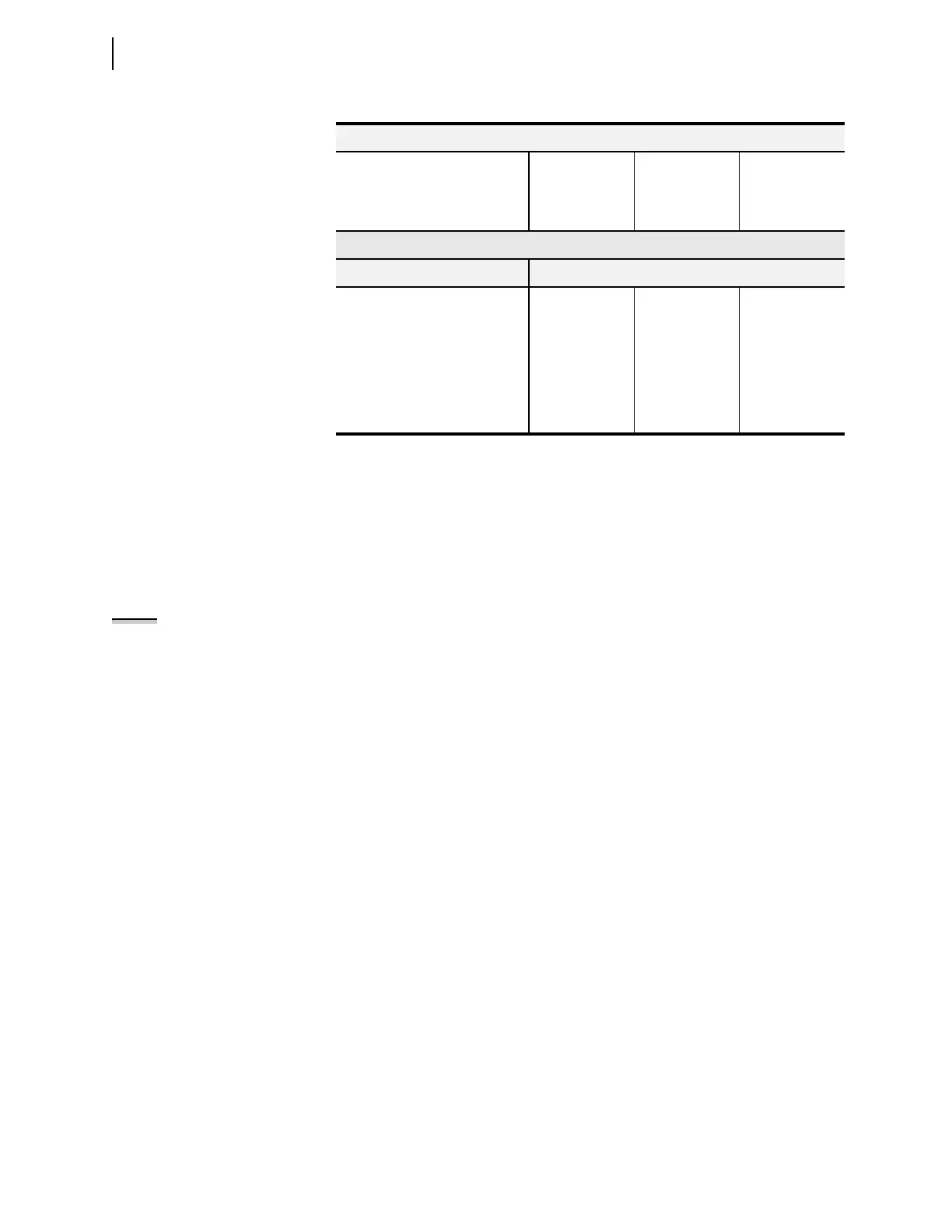
CS2
(forced air cooled ONAF)
MVA1CS2 = 140 MVA2CS2 = 140 MVA3CS2 = 140
CS3
(forced-oil and air cooled OFAF)
MVA1CS3 = 170 MVA2CS3 = 170 MVA3CS3 = 170
ETHERM = W
Cooling System MVA Rating
Winding 1 Winding 2 Winding 3
CS1
(natural oil and air cooled ONAN)
MVA1CS1 = 100 MVA2CS1 = 100 MVA3CS1 = 10
CS2
(forced air cooled ONAF)
MVA1CS2 = 140 MVA2CS2 = 140 MVA3CS2 = 14
CS3
(forced-oil and air cooled OFAF)
MVA1CS3 = 170 MVA2CS3 = 170 MVA3CS3 = 17
Table 5.13 Examples of Cooling Stages and MVA Ratings
ETHERM = 1
NOTE: x designates the transformer
and y designates the cooling stage.