5.28
SEL-2414 Transformer Monitor Instruction Manual Date Code 20130214
Metering and Monitoring
Monitoring
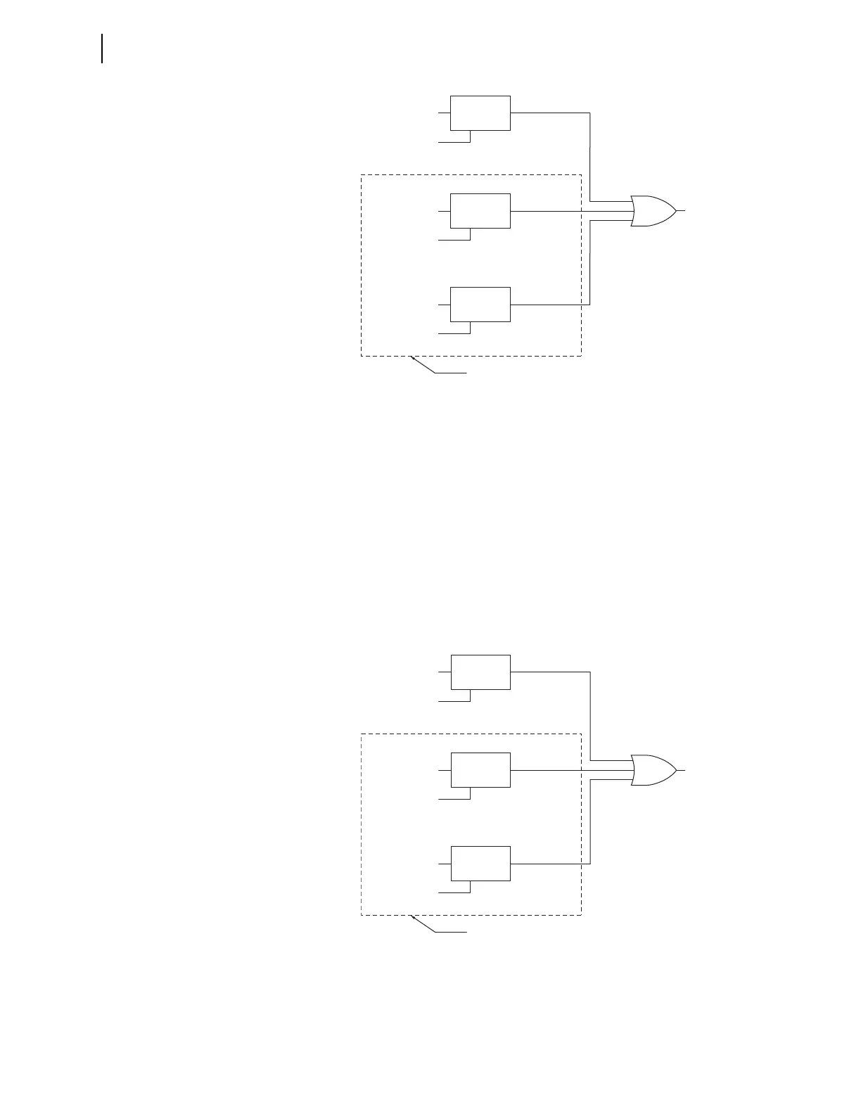
Figure 5.20 Daily Rate of Loss-of-Life Alarm Logic
Total Loss-of-Life Limit (TLOLL)
Range: 0–99%, in 0.01% steps
One of the outputs the thermal element provides is total loss of life, which is an
estimate of the accumulated loss of transformer insulation life as a percentage of
normal expected transformer insulation life. TLOLL determines a limit for total
loss of life. If the total loss of life exceeds the limit, a TLL Device Word bit
asserts. Using SEL
OGIC control equations, you can configure the TLL Device
Word bit to close an alarm contact.
When ETHERM = 3 or ETHERM = W, total loss-of-life is calculated for each of
the three individual windings. The TLL Device Word bit asserts when any of the
three values exceeds the limit. The thermal report will show which transformer
exceeded the limit.
Figure 5.21 Total Loss-of-Life Alarm Logic
T1RLOL or W1RLOL
RLL_1, W1_RLL
RLL_2, W2_RLL
RLL_3, W3_RLL
Winding 1
RLL Logic
RLOLL
(Setting)
T2RLOL or W2RLOL
RLOLL
(Setting)
T3RLOL or W3RLOL
RLOLL
(Setting)
ENABLED IF ETHERM = 3 OR W
RLL
Winding 2
RLL Logic
Winding 3
RLL Logic
T1TLOL or W1TLOL
TLL_1, W1_TLL
TLL_2, W2_TLL
TLL_3, W3_TLL
Winding 1
TLL Logic
TLOLL
(Setting)
T2TLOL or W2TLOL
TLOLL
(Setting)
T3TLOL or W3TLOL
TLOLL
(Setting)
ENABLED IF ETHERM = 3 OR W
TLL
Winding 2
TLL Logic
Winding 3
TLL Logic