5.29
Date Code 20130214 Instruction Manual SEL-2414 Transformer Monitor
Metering and Monitoring
Monitoring
Cooling System Efficiency Pickup (TxCSEP)
Range: 5°–100°C
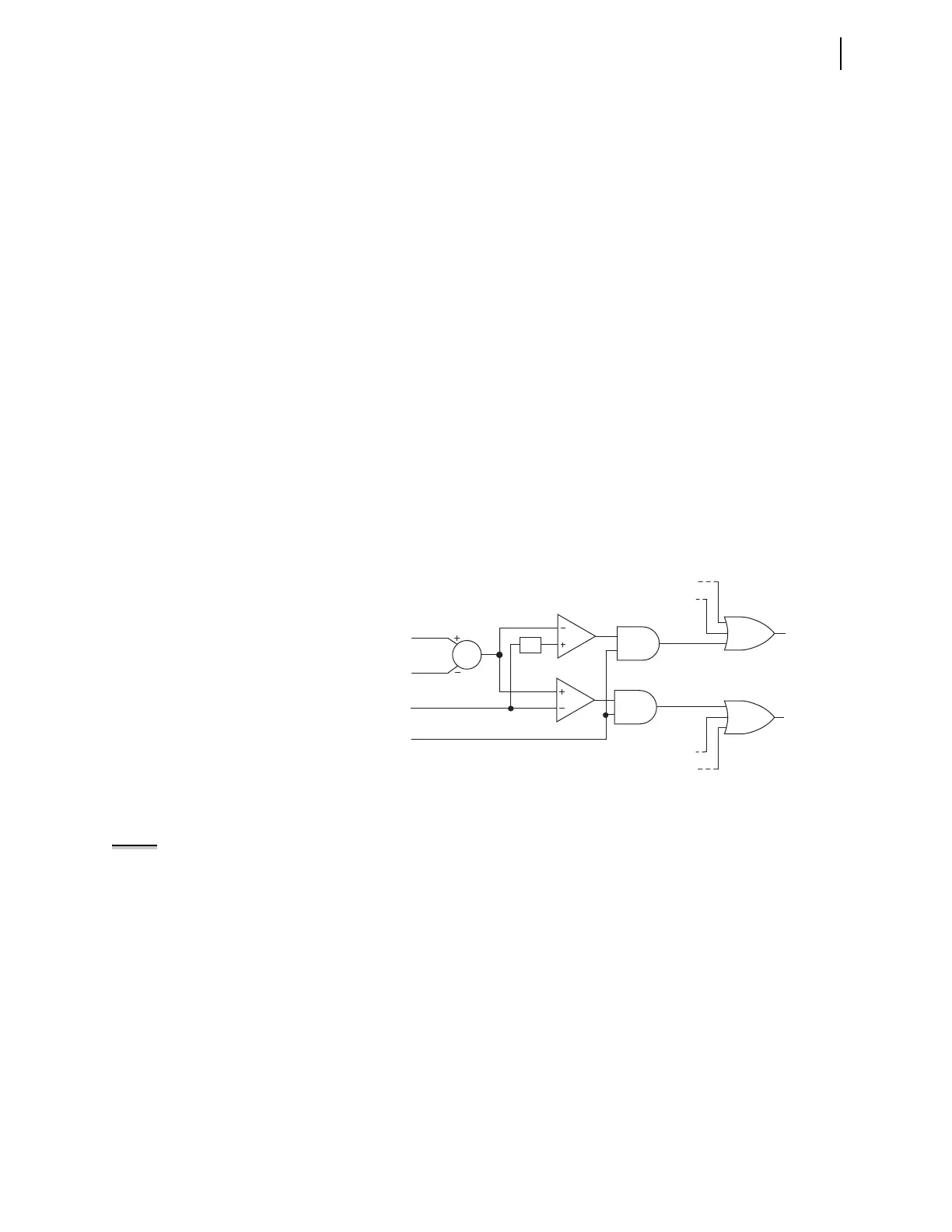
Figure 5.22 shows the logic the device uses to calculate the difference between
the measured top-oil temperature and the calculated top-oil temperature for
Transformer 1. If all probes are in order and all cooling stage constants settings
have been correctly chosen, you can use the element to verify the integrity of
both the cooling system and the measuring devices. Device Word bits CSE_x
(x = 1, 2, or 3) assert when the measured top-oil temperature is greater than the
calculated top-oil temperature, indicating that the cooling system (fans and/or
pumps) operates below the expected efficiency. Conversely, when the measured
top-oil temperature is lower than the calculated top-oil temperature, then Device
Word bits CSCM_x assert, indicating the wrong RTD or TC probe selection or
incorrect cooling stage constants settings. Device Word bit CSCM is the OR
combination of the CSCM_x Device Word bits, and Device Word bit CSE is the
OR combination of the CSE_x Device Word bits.
The thermal model may not calculate the same top-oil temperature that the RTD
measures. It is, therefore, prudent to set TxCSEP to a relatively large value at
first, then reduce it to more closely match the maximum observed difference
between the calculated and measured value.
When ETHERM = 3, cooling system efficiency is calculated for each of the three
single-phase transformers. The CSE Device Word bit is set when any of the three
values exceeds the limit. The thermal report will show which transformer
exceeded the limit.
Figure 5.22 Cooling System Efficiency Logic
General Cooling System Constants
Normal Insulation Life (TRLIFE).
Range: 1000–999999 hours, in 1-hour steps
IEEE C57.91: 1995 suggests that normal transformer insulation life is 20.55
years or 180000 hours. Default Transformer Constants lists this default value.
You can select other values within a range of 1000–999999 hours. When
installing a Transformer Monitor on an older transformer, you may set TRLIFE
to a value that accounts for some of the insulation life that has been used already.
Enable Default Constants (EDFTC).
Range: Y, N
Setting EDFTC enables or disables the default transformer cooling stage
constants in Default Transformer Constants, as listed in Table 5.14.
T1_OILM
T1_OILC
T1CSEP
(Setting)
MTO1_OK
CSCM_2
CSCM_3
CSCM_1
CSE_1
CSE_2
CSE_3
-1
CSE
CSCM
Σ
NOTE: In the following settings, x
designates a transformer and y
designates the cooling system that
the transformer uses. If ETHERM = 1,
x = 1. If ETHERM = 3, x = 1, 2, and 3. If
ETHERM = W, x = 1, 2, and 3.
If the transformers cooling stage is
passive cooled, y = 1. For a
transformer cooled by forced air, y = 2.
For a transformer with second stage
forced cooling, y = 3.